Page Tree
Previous Releases
This driver is used for slave (or server) mode communication with remote IEDs (Intelligent Electronic Devices) using Level 2 DNP 3.0 protocol in master (or client) mode. Communication can be established through a multi-point serial channel or a LAN using Ethernet and TCP-IP. In the latter case, each IED has an IP address..
Communication Driver Name: DNP30S
Implementation DLL: T.ProtocolDriver.DNP30S.dll
Protocol: DNP3.0 Slave standard protocol
Interface: TCP/IP or Serial
IEDs types supported: Any DNP 3.0-compatilble IED in master (or client) mode
Communication block size: Maximum 250 bytes, FT 1.2 format
Protocol Options: “LinkConfirm” mode and master station address
Multi-threading: User defined, five threads per communication node by default
Max number of nodes: User defined
PC Hardware requirements: Standard PC Ethernet interface board, RS485 or RS232 port
The table below shows the DNP objects and variants supported by this implementation.
| Object | Requisition (Master) | Response (Server) | ||||
|---|---|---|---|---|---|---|
| Obj | Var | Description | Function Codes (Decimal) | Qualifier Codes (Hex) | Function Codes (Decimal) | Function Codes (Decimal) |
| 1 | 0 | Binary Input (any variation) | 1 | 00,01,06 | ||
| 22 | 00,01,06 | 129 | ||||
| 1 | 1 | Single Bit Binary Input (packed) | 1 | 00,01,06 | 129 | 00, 01 |
| 1 | 2 | Binary Input with status | 129 | 00, 01 | ||
| 2 | 0 | Binary Input event (any variation) | 1 | 06,07,08 | ||
| 2 | 1 | Binary Input change without time | 1 | 06,07,08 | 129,130 | 17,18 |
| 2 | 2 | Binary Input change with absolute time | 1 | 06,07,08 | 129,130 | 17,18 |
| 2 | 3 | Binary Input change with relative time | 1 | 06,07,08 | 129,130 | 17,18 |
| 3 | 0 | Double-bit Binary input – Any variation | 22 | 00,01,06 | ||
| 3 | 1 | Double-bit Binary Input – Packed | 1 | 00,01,06 | 129 | 00, 01 |
| 3 | 2 | Double-bit Binary Input – With fla gs | 1 | 00,01,06 | 129 | 00, 01 |
| 4 | 0 | Double-bit Binary Input Event – A ny Variation | 1 | 06,07,08 | ||
| 4 | 1 | Double-bit Binary Input Event – w ithout time | 1 | 06,07,08 | 129,130 | 17,18 |
| 4 | 2 | Double-bit Binary Input Eventwith absolute time | 1 | 06,07,08 | 129,130 | 17,18 |
| 4 | 3 | Double-bit Binary Input Event - with relative time | 1 | 06,07,08 | 129,130 | 17,18 |
| 10 | 1 | Binary Output – Any Variation | 1 | 00,01,06 | ||
| 10 | 2 | Binary Output – Status with flags | 1 | 00,01,06 | 129 | |
| 12 | 1 | Control relay output block | 3,4,5 | 17,28 | 129 | Echo of request |
| 20 | 0 | Binary Counter – All variations | ||||
| 20 | 1 | Counter – 32-bit with flag | 1 | 00,01,06 | 129 | 00, 01 |
| 20 | 2 | Counter – 16-bit with flag | 1 | 00,01,06 | 129 | 00, 01 |
| 20 | 5 | Counter – 32-bit without flag | 1 | 00,01,06 | 129 | 00, 01 |
| 20 | 6 | Counter – 16-bit without flag | 1 | 00,01,06 | 129 | 00, 01 |
| 21 | 0 | Frozen counter – All variations | ||||
| 21 | 1 | Frozen Counter – 32-bit with flag | 1 | 00,01,06 | 129 | 00, 01 |
| 21 | 2 | Frozen Counter – 16-bit with flag | 1 | 00,01,06 | 129 | 00, 01 |
| 21 | 3 | Frozen Counter – 32-bit without f lag | 1 | 00,01,06 | 129 | 00, 01 |
| 21 | 4 | Frozen Counter – 16-bit without f lag | 1 | 00,01,06 | 129 | 00, 01 |
| 22 | 0 | Counter Event – Any Variation | 1 | 06 | ||
| 22 | 1 | Counter Event – 32-bit with flag | 1 | 06,07,08 | 129,130 | 17,18 |
| 22 | 2 | Counter Event – 16-bit with flag | 1 | 06,07,08 | 129,130 | 17,18 |
| 23 | 0 | Frozen Counter Event – Any Varia tion | 1 | 06,07,08 | ||
| 23 | 1 | Frozen Counter Event – 32-bit wi th flag | 1 | 06,07,08 | 129,130 | 17,18 |
| 23 | 2 | Frozen Counter Event – 16-bit wi th flag | 1 | 06,07,08 | 129,130 | 17,18 |
| 30 | 0 | Analog Input – All variations | 1, 22 | 00,01,06 | ||
| 30 | 1 | 32 Bits Analog Input | 1 | 00,01,06 | 129 | 00, 01 |
| 30 | 2 | 16 Bit Analog input with flag | 1 | 00,01,06 | 129 | 00, 01 |
| 30 | 3 | 32 Bits Analog Input without flag | 1 | 00,01,06 | 129 | 00, 01 |
| 30 | 4 | 16 Bit Analog input without flag | 1 | 00,01,06 | 129 | 00, 01 |
| 30 | 5 | Short Floating Point (32bits) | 1 | 00,01,06 | 129 | 00, 01 |
| 32 | 0 | Analog Input event – All variations | 1 | 06,07,08 | ||
| 32 | 1 | 32 Bits Analog Input event | 1 | 06,07,08 | 129,130 | 17,18 |
| 32 | 2 | 16 Bit Analog event without flag | 1 | 06,07,08 | 129,130 | 17,18 |
| 32 | 3 | 32 Bit Analog event with flag | 1 | 06,07,08 | 129,130 | 17,18 |
| 32 | 4 | 16 Bit Analog event with flag | 1 | 06,07,08 | 129,130 | 17,18 |
| 32 | 5 | Analog input event single float –without time | 1 | 06,07,08 | 129,130 | 17,18 |
| 32 | 7 | Analog input event single float –with time | 1 | 06,07,08 | 129,130 | 17,18 |
| 40 | 0 | Analog Output Status – Any variation | 1 | |||
| 40 | 1 | Analog Output Status – 32bits with flag | 1 | 00,01,06 | 129 | 00, 01 |
| 40 | 2 | Analog Output Status - 16bits with flag | 1 | 00,01,06 | 129 | 00, 01 |
| 40 | 3 | Analog output status – Single float with flag | 1 | 00,01,06 | 129 | 00, 01 |
| 41 | 1 | 32Bit Analog output block | 3,4,5,6 | 17,28 | 129 | Echo of request |
| 41 | 2 | 16 Bit Analog output block | 3,4,5,6 | 17,28 | 129 | Echo of request |
| 41 | 3 | Analog output block – Single float | 3,4,5,6 | 17,28 | 129 | Echo of request |
| 50 | 1 | Time and Data – Absolute time | 1,2 | 0x07 | 129 | 07 |
| 51 | 1 | Time and Date CTO – Absolute ti me, synchronized | 129,130 | 07 | ||
| 51 | 2 | Time and Date CTO – Absolute ti me, unsynchronized | 129,130 | 07 | ||
| 52 | 1 | Time Delay – Coarse | 129 | 07 | ||
| 52 | 2 | Time Delay – Fine | 129 | 07 | ||
| 60 | 1 | Class 0 data | 1 | 0x06 | ||
| 60 | 2 | Class 1 data | 1,20,21 | 06,07,08 | ||
| 60 | 3 | Class 2 data | 1,20,21 | 06,07,08 | ||
| 60 | 4 | Class 3 data | 1,20,21 | 06,07,08 | ||
| 80 | 1 | Internal indications | 1,2 | 00,01 | 129 | 01 |
In master mode protocol implementation, the master only performs the requests highlighted in blue. The server equipment responds using the answers highlighted in yellow. Note that it is up to the server equipment to decide how to respond and the master must support all the features of level 2 to be used as a possible answer.
The objects, object variations, function codes and qualifiers have their standard meanings in DNP. Tables with the function code and qualifiers are shown below:
| Function Code | Description | Origin |
|---|---|---|
| 1 | Read | Master |
| 2 | Write | Master |
| 3 | Select | Master |
| 4 | Operate | Master |
| 5 | Direct Operate (without selection) | Master |
| 6 | Direct Operate (without ack) | Master |
| 7 | Freeze Immediately | Master |
| 8 | Freeze Immediately (without ack) | Master |
| 9 | Freeze and Clear | Master |
| 10 | Freeze and Read | Master |
| 13 | Restart (Cold) | Master |
| 14 | Restart (Warm) | Master |
| 20 | Enable non-requested messages | Master |
| 21 | Disable non-requested messages | Master |
| 22 | Assigns class for an object | Master |
| 23 | Measurement with delay | Master |
| 129 | Response | Slave |
| 130 | Non-Requested Response (doesn´t exist on level 2) | Slave |
| Qualifier Code | Use on Request | Use on Response |
|---|---|---|
| 00,01 | Static Points range (class 0) or a single point with a number | Static Object |
| 06 | All points | Invalid |
| 07,08 | A limited number of events A single point without number (this is a timestamp) | A single point without number (this is a timestamp) |
| 17, 28 | Controls (one or more unrelated points) | Event Objects (one or more unrelated points) |
DNP has the concept of data classes, with four classes defined:
Class 0 : Corresponds to the static points, analog or digital. Its content is the value of an analog or digital variable, input or output in a given time;
Class 1, 2 and 3 : Events corresponding to class 0 variable transitions, state transitions or internal relay situations that causes an event.
A common practice in DNP IEDs is to associate the state variation of digital variables or the dead band pass of analog variables with class 1, 2 or 3 events. Thus, modifying the state/value of these variables will cause events to be transmitted at the request of the respective classes of events (60/2, 60/3 and 60/4). Periodically, a class 0 reading (60/1) may be requested for checking integrity.
Note
The normal slave sequence operation is shown below.
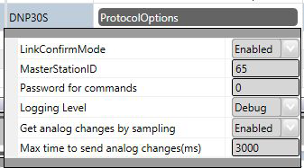
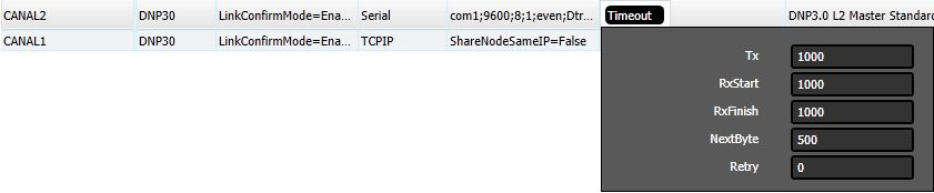
LinkConfirmMode – Protocol mode in which, in link layer, all requests should be confirmed by the remote IED. The default content is “Enabled.”
MasterStationID - A univocal number between 1 and 65534 corresponding to the master station address. This way, the master informs its own address to the slave when sending it a message. Some slaves reply to the master disregarding this number, while others demand that the address declared on the slave match the one from the master. The default for this field is “65534.”
Password for commands : In order to increase the security in sending commands, normally initiated only by a change in the state of a tag, it is possible to specify in the Client modules a password of up to 9 digits for the command. Here in this server module you must specify the password to generate the command for the Client module that will actually send the command to the field. This password must be the same as that used by the module sender of this command.
Logging Level – You can choose from this list the logging mode created by the communication module.
| Logging Level | |||
|---|---|---|---|
| Debug | Info | Warning | Error |
| All messages are registered in the LOG. | Only Info, Warning and Error messages are registered in the LOG. | Only Warning and Error messages are registered in the LOG. | Only Error messages are registered in the LOG. |
Get analog changes by sample - Alternatively to the mode of receiving changes of tag values, by using AccessType with WriteEventEnable, there’s an option to use, by the communication module, the sampling mode of changes occurred in tags. In this mode, the current values are checked against the last values sent periodically. This way only the change is considered, and the new value is sent to the client, if the absolute difference between the current value and the last one sent is greater than the Deadband attribute of the tag. To use this mode you must use the AccessType in the Points table, for these measurement tags, with WriteEventEnable disabled.
Max time to send analog changes (ms) - If you use the Get analog changes by sampling mode, this is the time to be used as the interval between two samples. The default time is set to 3 seconds.
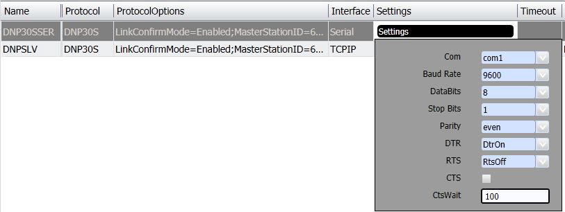
Serial Channel:
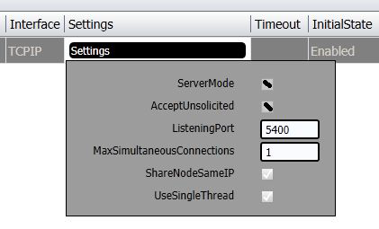
TCP/IP channels:
Defines limit times for transmission and reception of message characters and the number of retries.
Defines how the channel will initiate: enabled or disabled. If the channel is disabled, no message will be sent or received through it. In other words, the channel will be deactivated.

Each node represents a remote station (IED). The user can configure multiple workstations into a single channel for serial communication. In the case of TCP-IP communication, only one node is supported for each channel. In this case, you must set as many channels as there are nodes.
Attribute set associated with the node (channel), which refers to its address and other
attributes presented below:
 .
.
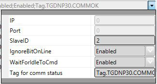
For TCP-IP Communication:
IP Address – Not used
Port – Not used
For both TCP-IP and Serial:
SlaveID – Slave station address, defined by this channel.
IgnoreBitOnLine – If “enabled,” it indicates the driver must ignore the “BitOnLine” indication which is inserted by the IED when a failure or normality occurs at a point, according to the IED criteria.
WaitForIdleToCmd – If “enabled,” it indicates that a command should only be sent when the sampled communication is at rest, i.e., is not happening.
Tag for Comm status - This field can indicate the name of an existing tag in the project to show success/failure in communication from a functional point of view. The module waits for a maximum of Timeout milliseconds (defined in Protocol Options, above) for receiving a request from the client. In case of failure, the value of this tag will be set to ZERO. In case of success, the value will be set as ONE.
Points can be input or output points.
Entry points, i.e. points that are acquired through the protocol, have basically two main parameters: point type and address.
Output points, used for remote controls, have besides the type and address, a parameter (ControlCode) for specifying the output operation. On SCADA, given an IED address map, address numbers must be unique for points of the same type.
Point states or point values are reported by IED through Information Objects defined in the standard. These objects have variations such as with or without “timestamp.” Every time the IED reports an Information Object with a “timestamp,” this will be listed on SCADA as an attribute of the point that corresponds to this object. When there is no “timestamp,” SCADA will fill it with the current time of the computer hosting SCADA.
SCADA communication module on Server mode implements:
The implemented SCADA point types, listed below, are defined based on the data objects set out in the standard. For each type of point, whichever the object variation received on the IED might be, with or without a flag or a timestamp, the values acquired will be placed in points with the types listed below. In the Points table, the “ Address ” field is used to choose the type of point and to specify its address.
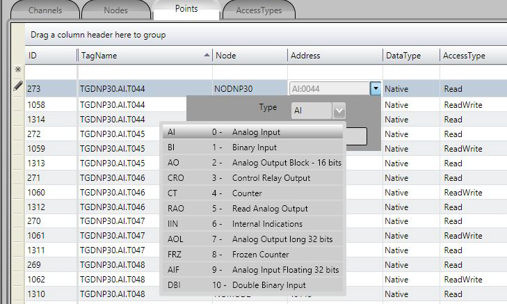
AI - Analog Input Scalar analog measurement used for transmission of analog quantities. The tag data with this type of point is sent through object 32 variation 1, when sent as events; when sending by class 0 (static), it uses object 30 variation 1.They are 32-bit integer numbers without timestamp.
BI - Binary Input Simple bitwise input point, value 0 or 1. The data of tags with this type of point is sent through object 2 variation 2, when by reason of change (event), with timestamp, or through object 2 var. 1, when for general reading (class 0).
DBI - Double-bit Binary Input Double binary input point, value between 0 and 3. The tag data with this type of point is sent through object 3 and variation 2, when by reason of change (event), with timestamp, or through object 3 var. 1, when for general reading (class 0).
RAO - Read Analog Output Not used in the implementation of slave mode.
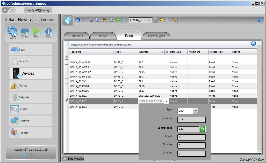
CRO - Control Relay Output Digital output point used to receive switch and breaker commands. The DNP 12 object, including the Control Code (8 bits), is expected to indicate the type of command and execution details. When registering these points in slave mode, it is necessary to define a control code that is identical to the one that will be sent by the Master IED, in order to identify the tag used in the Slave. The slave only executes the change of the value of the SCADA point. In order for the command to reach its final destination in an IED, the affected tag must be used by another Client protocol, which will send it to the IED. In the case of control of switches and circuit breakers it is recommended that two tags be used: one for Trip and one for Close. The possible values received from the client are shown in the table below with their associated actions:
| ControlCode | Protocol Action | Action in SCADA tag executed on the slave |
|---|---|---|
| 1 | Output Pulse ON | Changes to 1 and later to zero |
| 2 | Output Pulse OFF | Changes to zero and later to 1 |
| 3 | Output Latch ON | Changes to 1 |
| 4 | Output Latch OFF | Changes to zero |
| 65 | Output Pulse ON + Close | Changes to 1 and later to zero |
| 66 | Output Pulse OFF + Close | Changes to zero and later to 1 |
| 67 | Output Latch ON + Close | Changes to 1 |
| 68 | Output Latch OFF + Close | Changes to zero |
| 129 | Output Pulse ON + Trip | Changes to 1 and later do zero |
| 130 | Output Pulse OFF + Trip | Changes to zero and later to 1 |
| 131 | Output Latch ON + Trip | Changes to 1 |
| 132 | Output Latch OFF + Trip | Changes to zero |
| + 16 | Queue + Trip | Does nothing |
| + 32 | Clear + Trip | Does nothing |
CT – Counter Binary counter of 16 or 32 bits, received from the IEDs through objects 20 and all their
variations. This number has the last state of counter, at the instant it is read.
FRZ - Frozen Counter Binary counter of 32 bits, sent through an object 21 variation 1, which contains the
information of a counter used as a tag.
AO - Analog Output Status or Block (16bits) When this slave mode receives a message with a writing Function Code (2 = Write or 4 = Operate or 5 = DirectOperate) and this object 41 (required value to be reached on the analog
output) on its 2 variations (16 bits), this value is written on the tag defined by the POINTS table for the address received on the object.
AOL - Analog Output Long (32 bits) When this slave mode receives a message with a writing Function Code (2 = Write) and this object 41 (required value to be reached on the analog output) on its 1 variation (32 bits), this value is written on the tag defined by the POINTS table for the address received on the object.
AIF - Analog Input Floating (32 bits) Measurement used for analog transmission of analog quantities. Tags with this type must be identified as real on SCADA. Their value is sent through object 30 with variation 5, when sending static by class 0, or using object 32 variation 5 when sent as event changes.. These are floating point numbers with 32 or 64 bits, IEEE-754 format.
IIN - Internal Indications As a standard of this protocol, the Internal Indications statuses or the command answer
statuses are sent in every slave answer message, for client use. The following table shows the format of these two 16-bit words.
IIN: 16 bits sent in every slave answer with control data - Address: 65000
| BIT | Origin | Description | Content |
|---|---|---|---|
| 0 | IIN | Broadcast | Returns 1 if slave receives a broadcast message (address = FFFF) |
| 1 | IIN | Class 1 | Returns 1 if slave has class 1 events |
| 2 | IIN | Class 2 | Returns 1 if slave has class 2 events |
| 3 | IIN | Class 3 | Returns 1 if slave has class 3 events |
| 4 | IIN | Clock Synchronization | Returns 1 if slave asks for clock synchronization |
| 5 | IIN | Outputs set to local | Returns 1 if slave has any output set to local |
| 6 | IIN | Problem | Returns 1 if slave has a problem |
| 7 | IIN | Restart | Returns 1 if slave has restarted |
| 8 | IIN | Function not Implemented | Returns 1 if a function asked by the master was not implemented in the slave |
| 9 | IIN | Unknown Object | Returns 1 if slave does not have a certain object at all or in a specific class |
| 10 | IIN | Invalid Data | Returns 1 if slave has an invalid parameter in the qualifier or the address range is invalid |
| 11 | IIN | Overflow | Returns 1 if slave buffer has an overflow |
| 12 | IIN | Busy | Returns 1 if the request was received but is already running |
| 13 | IIN | Corrupted Data | Returns 1 if the parametric data was corrupted |
| 14 | IIN | Reserved | Always 0 |
| 15 | IIN | Reserved | Always 0 |
Status field: 8 bits sent as an answer to a command. Address: 65001
| BIT | Origin | Description | Content |
|---|---|---|---|
| 0 | Status | Command Accepted | Returns 1 after a correct command |
| 1 | Status | Command Not Accepted | Returns 1 if a timeout has occurred between select and operate |
| 2 | Status | Select Fault | Returns 1 if an operate has occurred without prior select |
| 3 | Status | Format Error | Returns 1 if command has an error in format |
| 4 | Status | Control not supported | Returns 1 if operation was not supported |
| 5 | Status | Full Queue | Returns 1 if the request queue on the slave is full or the point is already active |
| 6 | Status | Hardware Error | Returns 1 if a hardware error occurred while the command was being processed |
| 7 | Not used |
The Address field to be filled in when registering a point is what the standard calls “Index.” It consists of a 16-bit number that is the indicative index [0 to n-1] of each of the points of the same type mapped within the IED.
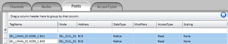
For example purposes, a points table filled with several types of points is presented below. The digital output type points (CRO), as mentioned above, have their control code, besides the address.
To implement discrete digital input points, it is enough to use the “Bit” attribute of a tag for each of the points that define the discrete digital input value. Therefore, for example, a switch with two contacts that define its state:
| Tag | Address | Complement |
|---|---|---|
| SEL_LINHA_01.SC89_1 | 8 | Switch Open |
| SEL_LINHA_01.SC89_1 | 9 | Switch Closed |
This is defined as an AnalogInt Tag and the Bit attribute of this 16-bit variable (AnalogInt) is
used on the node table to address two points, as in the figure below:
The values assumed by the SEL_LINHA_01.SC89_1 variable will be:
| Tag | Bit 0 | Bit 1 | Value | Meaning |
|---|---|---|---|---|
| SEL_LINHA_01.SC89_1 | 0 | 0 | 0 | UNDEFINED |
| SEL_LINHA_01.SC89_1 | 1 | 0 | 1 | OPEN |
| SEL_LINHA_01.SC89_1 | 0 | 1 | 2 | CLOSED |
| SEL_LINHA_01.SC89_1 | 1 | 1 | 3 | ERROR |
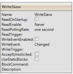
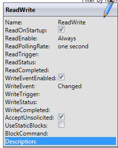
Since this is a communication module in client mode, it requires a few characteristics of its own for parametrization of the Access Type field in the Points table:
For reading or command reception-type points (using writeEventsEnable, for getting tag changes):
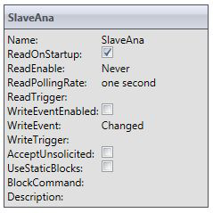
For measure-type points (analog) - (Using get analog changes by sampling: Option Get analog changes by sampling):
For command-type points:
Access Type must be defined ( as shown in the WriteSlave picture below )