Page Tree
Previous Releases
This driver is used for communication with remote IEDs (Intelligent Electronic Devices) using the protocol DNP 3.0 Level 2. Communication can be established through a multi-point serial channel or a LAN using Ethernet and TCP-IP. In the latter case, each IED has an IP address.
Communication Driver Name: DNP30
Current Version: 2016.2
Implementation DLL: T.ProtocolDriver.DNP30.dll
Protocol: DNP3.0 Master standard protocol
Interface: TCP/IP or Serial
IEDs types supported: Any DNP 3-compatilble IED
Communication Block Size: Maximum 250 bytes, FT 1.2 format
Protocol Options: “LinkConfirm” mode and master station address
Multi-threading: User defined, five threads per comunication node by default
Max number of nodes: User defined
PC Hardware requirements: Standard PC Ethernet interface board, RS485 or RS232 port
The table below shows the DNP objects and variants supported by this implementation.
Objects labeled L4 are implemented, but are defined at the L4 level.
| Object | Request (Master) | Response (Slave) | ||||
|---|---|---|---|---|---|---|
| Obj. | Var. | Description | Function Codes (Decimal) | Qualifier Codes (Hex) | Function Codes (Decimal) | Qualifier Codes (Hex) |
| 1 | 0 | Binary Input (any variation) | 1 | 00,01,06 | ||
| 22 | 00,01,06 | |||||
| 1 | 1 | Single Bit Binary Input (packed) | 1 | 00,01,06 | 129 | 00, 01 |
| 1 | 2 | Binary Input with status | 1 | 00,01,06 | 129 | 00, 01 |
| 2 | 0 | Binary Input event (any variation) | 1 | 06,07,08 | ||
| 2 | 1 | Binary Input change without time | 1 | 06,07,08 | 129,130 | 17,18 |
| 2 | 2 | Binary Input change with absolute time | 1 | 06,07,08 | 129,130 | 17,18 |
| 2 | 3 | Binary Input change with relative time | 1 | 06,07,08 | 129,130 | 17,18 |
| 3 | 0 | Double bit Binary input – Any variation –L4 | 22 | 00,01,06 | ||
| 3 | 1 | Double-bit Binary Input – Packed –L4 | 1 | 00,01,06 | 129 | 00, 01 |
| 3 | 2 | Double-bit Binary Input – With fla gs–L4 | 1 | 00,01,06 | 129 | 00, 01 |
| 4 | 0 | Double-bit Binary Input Event – A ny Variation–L4 | 1 | 06,07,08 | ||
| 4 | 1 | Double-bit Binary Input Event – w hitout time–L4 | 1 | 06,07,08 | 129,130 | 17,18 |
| 4 | 2 | Double-bit Binary Input Eventwith Absolute time–L4 | 1 | 06,07,08 | 129,130 | 17,18 |
| 4 | 3 | Double-bit Binary Input Event - with relative time–L4 | 1 | 06,07,08 | 129,130 | 17,18 |
| 10 | 1 | Binary Output – Any Variation | 1 | 00,01,06 | ||
| 10 | 2 | Binary Output – status with flags | 1 | 00,01,06 | 129 | 00,01 |
| 12 | 1 | Control relay output block | 3,4,5,6 | 17,28 | 129 | Echo of request |
| 20 | 0 | Binary Counter – all variations | 1,7,8,9,10 | |||
| 20 | 1 | Counter – 32-bit with flag | 1 | 00,01,06 | 129 | 00, 01 |
| 20 | 2 | Counter – 16-bit with flag | 1 | 00,01,06 | 129 | 00, 01 |
| 20 | 5 | Counter – 32-bit without flag | 1 | 00,01,06 | 129 | 00, 01 |
| 20 | 6 | Counter – 16-bit without flag | 1 | 00,01,06 | 129 | 00, 01 |
| 21 | 0 | Frozen counter – All variations | 1, 22 | |||
| 21 | 1 | Frozen Counter – 32-bit with flag | 1 | 00,01,06 | 129 | 00, 01 |
| 21 | 2 | Frozen Counter – 16-bit with flag | 1 | 00,01,06 | 129 | 00, 01 |
| 21 | 9 | Frozen Counter – 32-bit without f lag | 1 | 00,01,06 | 129 | 00, 01 |
| 21 | 10 | Frozen Counter – 16-bit without f lag | 1 | 00,01,06 | 129 | 00, 01 |
| 22 | 0 | Counter Event – Any Variation | 1 | 06 | ||
| 22 | 1 | Counter Event – 32-bit with flag | 1 | 06,07,08 | 129,130 | 17,18 |
| 22 | 2 | 2 Counter Event – 16-bit with flag | 1 | 06,07,08 | 129,130 | 17,18 |
| 23 | 0 | Frozen Counter Event – Any Varia tion | 1 | 06,07,08 | ||
| 23 | 1 | Frozen Counter Event – 32-bit wi th flag | 1 | 06,07,08 | 129,130 | 17,18 |
| 23 | 2 | Frozen Counter Event – 16-bit wi th flag | 1 | 06,07,08 | 129,130 | 17,18 |
| 30 | 0 | Analog Input – all variations | 1, 22 | 00,01,06 | ||
| 30 | 1 | 32 Bits Analog Input | 1 | 00,01,06 | 129 | 00, 01 |
| 30 | 2 | 16 Bit Analog input with flag | 1 | 00,01,06 | 129 | 00, 01 |
| 30 | 3 | 32 Bits Analog Input without flag | 1 | 00,01,06 | 129 | 00, 01 |
| 30 | 4 | 16 Bit Analog input without flag | 1 | 00,01,06 | 129 | 00, 01 |
| 30 | 5 | Short Floating Point (32bits) – L4 | 1 | 00,01,06 | 129 | 00, 01 |
| 32 | 0 | Analog Input event – All variations | 1 | 06,07,08 | 129,130 | 17,18 |
| 32 | 1 | Analog Input event - 32 Bits without time | 1 | 06,07,08 | 129,130 | 17,18 |
| 32 | 2 | Analog event without flag – 16 Bits – Without time | 1 | 06,07,08 | 129,130 | 17,18 |
| 32 | 3 | 32 Bit Analog event with flag – L4 | 1 | 06,07,08 | 129,130 | 17,18 |
| 32 | 4 | 16 Bit Analog event with flag– L4 | 1 | 06,07,08 | 129,130 | 17,18 |
| 32 | 5 | Analog input event single float –without time– L4 | 1 | 06,07,08 | 129,130 | 17,18 |
| 32 | 7 | Analog input event single float –with time– L4 | 1 | 06,07,08 | 129,130 | 17,18 |
| 40 | 0 | Analog Output Status–Any variation | 1 | |||
| 40 | 1 | Analog Output Status – 32bits with flag | 1 | 00,01,06 | 129 | 00, 01 |
| 40 | 2 | Analog Output Status - 16bits with flag | 1 | 00,01,06 | 129 | 00, 01 |
| 40 | 3 | Analog output status – Single float with flag –L4 | 1 | 00,01,06 | 129 | 00, 01 |
| 41 | 1 | Analog output block - 32Bit | 3,4,5,6 | 17,28 | 129 | Echo of request |
| 41 | 2 | Analog output block - 16 Bit | 3,4,5,6 | 17,28 | 129 | Echo of request |
| 41 | 3 | Analog output block – Single float - L4 | 3,4,5,6 | 17,28 | 129 | Echo of request |
| 50 | Time and Data – Absolute time | 1,2 | 0x07 | 129 | 07 | |
| 51 | Time and Date CTO – Absolute ti me, synchronized | 129,130 | 07 | |||
| 51 | Time and Date CTO – Absolute ti me, unsynchronized | 129,130 | 07 | |||
| 52 | Time Delay – Coarse | 129 | 07 | |||
| 52 | Time Delay – Fine | 129 | 07 | |||
| 60 | Class 0 data | 1 | 0x06 | |||
| 60 | Class 1 data | 1,20,21 | 06,07,08 | |||
| 60 | Class 2 data | 1,20,21 | 06,07,08 | |||
| 60 | Class 3 data | 1,20,21 | 06,07,08 | |||
| 60 | Internal indications | 1,2 | 00,01 | 129 | 01 | |
In master mode protocol implementation, the master only performs the requests highlighted in blue. The server equipment responds using the answers highlighted in yellow. Note that it is up to the server equipment to decide how to respond and the master must support all the features of level 2 to be used as a possible answer.
The objects, object variations, function codes and qualifiers have their standard meanings in DNP. Tables with the function code and qualifiers are shown below:
| Function Code | Description | Origin |
|---|---|---|
| 1 | Read | Master |
| 2 | Write | Master |
| 3 | Select | Master |
| 4 | Operate | Master |
| 5 | Direct Operate (without selection) | Master |
| 6 | Direct Operate (without ack) | Master |
| 7 | Freeze Immediately | Master |
| 8 | Freeze Immediately (without ack) | Master |
| 9 | Freeze and Clear | Master |
| 10 | Freeze and Read | Master |
| 13 | Restart (Cold) | Master |
| 14 | Restart (Warm) | Master |
| 20 | Enable non-requested messages | Master |
| 21 | Disable non-requested messages | Master |
| 22 | Assigns class for an object | Master |
| 23 | Measurement with delay | Master |
| 129 | Response | Slave |
| 130 | Non-Requested Response (doesn´t exist on level 2) | Slave |
| Qualifier Code | Use on Request | Use on Response |
|---|---|---|
| 00,01 | Static Points range (class 0) or a single point with a number | Static Object |
| 06 | All points | Invalid |
| 07,08 | A limited number of events A single point without number (this is a timestamp) | A single point without number (this is a timestamp) |
| 17, 28 | Controls (one or more unrelated points) | Event Objects (one or more unrelated points) |
DNP has the concept of data classes, with four classes defined:
Class 0 : Corresponds to the static points, analog or digital. Its content is the value of an analog or digital variable, input or output, at a given time.
Class 1, 2 and 3 : Events corresponding to class 0 variable transitions, state transitions or
internal relay situations that causes an event.
A common practice in DNP IEDs is to associate the state variation of digital variables or the dead band pass of analog variables with class 1, 2 or 3 events. Thus, modifying the state/value of these variables will cause events to be transmitted at the request of the respective classes of events (60/2, 60/3 and 60/4). Periodically, a class 0 reading (60 / 1) may be requested for checking integrity.
Note
Static variables not assigned to a class do not cause events.
Class and variable association should be performed on the IED, using an appropriate program. The SCADA runs data acquisition through the classes, however, without defining which variable belongs to which class.
The normal master sequence operation is shown below:
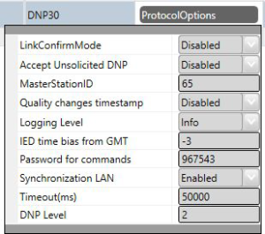
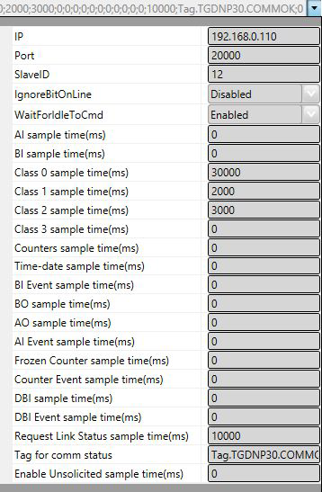
LinkConfirmMode – Protocol mode in which, in the link layer, all requests should be confirmed by the remote IED. The default content is “Enabled.”
Accept Unsolicited DNP – Enabling this option causes an Enable Unsolicited Messages message (Function Code = 20) to be sent out from the master to the slave at the start of a channel execution, right after the Class 0 request and every time the master receives a “RESTART” indication in the Internal Indications field..
MasterStationID - A univocal number between 1 and 65534 corresponding to the master station address. This way, the master informs its own address to the slave when sending it a message. Some slaves reply to the master disregarding this number, while others demand that the address declared on the slave match the one from the master. The default for this field is “65534.”
Quality changes timestamp – Enabling this option will lead to alteration in the tag present timestamp when a new reading of a flagged object is received, even if there is no alteration to the tag status (value), but there is quality alteration.
Logging Level – You can choose from this list the logging mode created by the communication
module.
| Logging Level | |
|---|---|
| Debug | All messages are registered in the LOG. |
| Info | Only Info, Warning and Error messages are registered in the LOG. |
| Warning | Only Warning and Error messages are registered in the LOG. |
| Error | Only Error messages are registered in the LOG. |
IED time bias from GMT – On SCADA, internally, all timestamps are stored with GMT (UTC) dates. IEDs usually send these dates also in GMT, and no correction is made. The default for this option is Zero. If in the current implementation the IEDs send the timestamps in their local time, the difference between this time and GMT time must be specified here. For example in Brasilia the local time is 3 hours less than GMT. In this case, -3 should be specified in this table.
Password for commands: To increase the security of sending commands, normally initiated only by a change in the state of a tag, it is possible here to specify a password of up to nine digits. The communication module will, at the moment the command is received, verify this password against the current value of the EstimatedValue attribute tag involved in the command. Therefore, in the operation of sending a command through a window, script, etc. this number must be loaded in this attribute. The communication module, after executing the command, changes the value of EstimatedValue to ZERO. This verification does not occur if this option is left as zero.
Synchronization LAN – Indicates the synchronization method to be used by the driver, according to the device to which it communicates. Choose ENABLE to use the LAN Synchronization method.
Timeout (ms) – Waiting time in milliseconds for receiving a response after sending any request. It is a functional check, which does not take into account the type of request or response, and it only verifies if there are responses being received in the channel.
Dnp30 Level - By default, the Level 3 profile is used. If you want the operation as level 2, you can enter here the number 2. The client will not use objects and functions available in level 3, such as enabling and disabling Dynamic Unsolicited and requests of several classes in the same message.
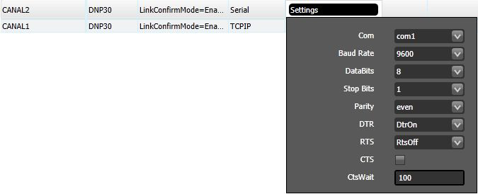
Serial and Multiserial Channel:
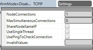
TCP/IP channels:
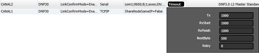
Defines limit times for transmission and reception of message characters and the number
of retries.
Defines how the channel will initiate: enabled or disabled. If the channel is disabled, no message will be sent or received through it. In other words, the channel will be deactivated.

Each node represents a remote station (IED). The user can configure multiple workstations into a single channel for serial communication. In the case of TCP-IP communication, only one node is supported for each channel. In this case, the user must set as many channels as there are nodes.
Attribute set associated with the node (channel), which refers to its address and other attributes presented below:
For TCP-IP Communication:
Note
In the case of serial communication, these two first fields do not exist.
For any case:
Points can be input or output points.
Entry points, i.e. points that are acquired through the protocol, have basically two main parameters: point type and address.
Output points, used for remote controls, have a “Control Code” parameter in addition to the type and address to specify the output operation. In the address map of an IED the addresses restart for each type of point.
The states or values of the points are reported by the IED by Information Objects defined in the protocol. These objects have variations such as with or without timestamp. Whenever the IED reports with a “timestamp” it will be used in the corresponding attribute of a point on SCADA. When it does not come with a “timestamp” the driver will put the current time of the computer where the driver is running as “timestamp.”
SCADA communication module on master mode implements:
The implemented SCADA point types, listed below, are defined based on the data objects set out in the standard. For each type of point, whichever the object variation received on the IED might be, with or without a “flag” or a timestamp, the values acquired will be placed in points with the types listed below. In the Points table, the “ Address ” field is used to choose the type of point and to specify its address.
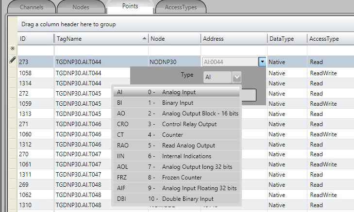
AI - Analog Input - Scalar analog measurement used for transmission of analog quantities. Used to receive
data sent through objects 30 and 32 and all their variations. They are 16 or 32-bit integers.
BI - Binary Input- Simple binary entry point, value 0 or 1. Used to receive data sent through objects 1 and 2
and all their variations.
DBI - Double Binary Input - Dual binary input point, value between 0 and 3. Used to receive data sent through objects 3 and 4 and all their variations.
RAO – Read Analog Output - Point for reading the contents of analog output of 16 bits or 32 bits. Used for the reception of objects of types 40 and 41.
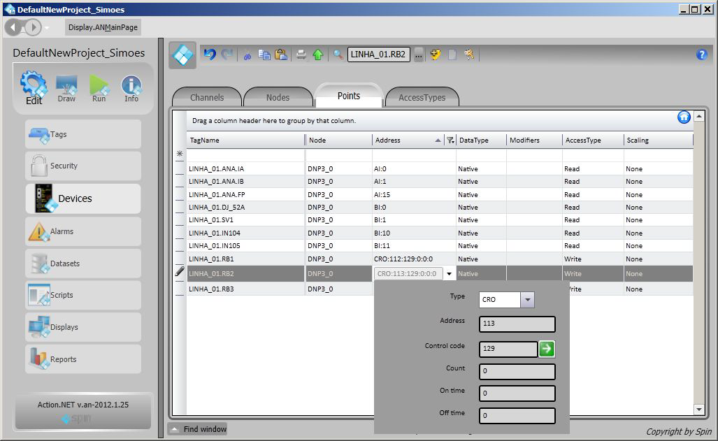
CRO - Control Relay Output - Digital output point used to control the switches and circuit breakers. The DNP object 12, including a Control Code (8 bits), is used to indicate the type of command and execution details. When chosen, a field will show requesting this code information. After clicking on the right arrow, a window with the selected attributes for the present value will appear. If the user changes the selected attributes and presses the return arrow, a new value associated with the selected attributes will be generated.
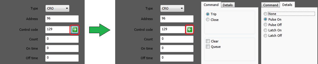
The possible values are presented in the table below with the respective associated actions:
| Control Code | Action |
|---|---|
| 1 | Output Pulse ON |
| 2 | Output Pulse OFF |
| 3 | Output Latch ON |
| 4 | Output Latch OFF |
| 65 | Output Pulse ON + Close |
| 66 | Output Pulse OFF + Close |
| 67 | Output Latch ON + Close |
| 68 | Output Latch OFF + Close |
| 129 | Output Pulse ON + Trip |
| 130 | Output Pulse OFF + Trip |
| 131 | Output Latch ON + Trip |
| 132 | Output Latch OFF + Trip |
| +16 | Queue + Trip |
| +32 | Clear + Trip |
funcCode – In the commands it’s possible also to define the operation to be executed in the command according to the following table:
| funcCode | Action |
|---|---|
| 3 | Select |
| 4 | Operate |
| 5 | Direct Operation (no selection) |
| 6 | Direct Operation (without ack) |
| 34 | Select and Operate |
Note: Code 5 will be used if no code is chosen.
CT – Counter - Binary counter of 16 or 32 bits, received from the IEDs through type 20 objects and all their variations. This number has the last state of counter, at the instant it is read.
FRZ - Frozen Counter - Binary counter of 16 or 32 bits, received from the IED through object 21 and its variations, which contains information on the last time a counter was “frozen.” The frozen value shows the value of the counter (the same index) when the last freeze operation was performed on the counter of the slave IED.
AO - Analog Output Status or Block (16bits) - Analog output for a 16-bit DA converter, using type 40 objects (actual value to be applied to the drive) or type 41 objects (amount required to be achieved in the analogue output), both on variation 2 (16 bits).
AOL - Analog Output long (32 bits) - Analog output for a 32-bit DA converter, using type 40 objects (actual value to be applied to the drive) or type 41 objects (amount required to be achieved in the analogue output), both on variation 1 (32 bits).
AIF - Analog Input Floating (32 bits) - Measurement used for analog transmission of analog quantities. Used to receive data sent over type 100 objects and all their variations. Floating point numbers are 32 or 64-bit IEEE-754 format.
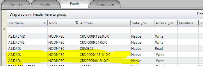
CRS – Control Relay Signaling - A type defined for SCADA for setting the match between the output tag and the input tag that performs the signaling, as a result of the command. When the CRS type is chosen, in the definition of the Address column, a different menu appears with the fields to define the necessary parameters.
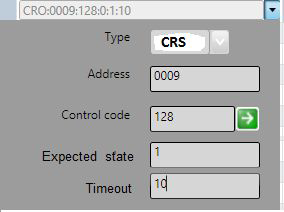
The following figure shows the setting in the POINTS table. The signaling comes in tag A2.DJ.DJ, which is of type DBI. The two lines highlighted in yellow show the definition of the signaling of commands with the same address (0009) and control code (128 - Open and 64 - Close).
These two lines are used to load the protocol module to create a static list with all matches on the node. Their information does not create new points in real time.
Nothing else is required for setup. With this list, the module will automatically call the transaction creation and verification methods. The command signaling is only used for digital CRO commands and BI and DBI digital signals.
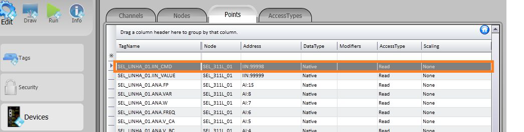
IIN - Internal Indications - On this implementation, it is possible to get access to the internal indication statuses or to the response status of commands by defining tags with the IIN type, for these to receive this information from the communication module. These IED internal indication statuses are reported through flags placed on the objects transmitted in the communication.
In order to receive the IIN, an analog int tag must be defined as IIN type and 65000 address. This tag will receive the register with the bits whose meaning are presented in the table below.
In order to receive the statuses from the most recently sent commands, an analog int tag must be defined as IIN type and 65001 address.
IIN: 16 16 bits sent in every slave answer with control data - Address: 65000
| Bit | Origin | Description | Content |
|---|---|---|---|
| 0 | IIN | Broadcast | Returns 1 if slave receives a broadcast message (address = FFFF) |
| 1 | IIN | Class 1 | Returns 1 if slave has class 1 events |
| 2 | IIN | Class 2 | Returns 1 if slave has class 2 events |
| 3 | IIN | Class 3 | Returns 1 if slave has class 3 events |
| 4 | IIN | Clock Synchronization | Returns 1 if slave asks for clock synchronization |
| 5 | IIN | Outputs set to local | Returns 1 if slave has any output set to local |
| 6 | IIN | Problem | Returns 1 if slave has a problem |
| 7 | IIN | Restart | Returns 1 if slave has restarted |
| 8 | IIN | Function not Implemented | Returns 1 if a function asked by the master was not implemented in the slave |
| 9 | IIN | Unknown Object | Returns 1 if slave does not have a certain object at all or in a specific class |
| 10 | IIN | Invalid Data | Returns 1 if slave has an invalid parameter in the qualifier or the address range is invalid |
| 11 | IIN | Overflow | Returns 1 if slave buffer has an overflow |
| 12 | IIN | Busy | Returns 1 if the request was received but is already running |
| 13 | IIN | Corrupted Data | Returns 1 if the parametric data was corrupted |
| 14 | IIN | Reserved | Always 0 |
| 15 | IIN | Reserved | Always 0 |
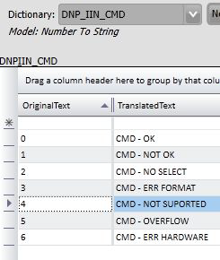
Status field: 8 bits sent as an answer to a command. Address: 65001
| Byte Value | Origin | Description | Content |
|---|---|---|---|
| 0 | Status | Command Accepted | after a correct command |
| 1 | Status | Command Not Accepted | a timeout has occurred between select and operate |
| 2 | Status | Select Fault | operate has occurred without a prior select |
| 3 | Status | Format Error | command has a format error |
| 4 | Status | Control not supported | operation is not supported |
| 5 | Status | Full Queue | the request queue on the slave is full or the point is already active |
| 6 | Status | Hardware Error | a hardware error occurred while the command was being processed |
| 7 to 127 | Not used |
These IIN can be defined in dictionaries and shown on event lists and/or alarms. This way, for example purposes, a dictionary associated with a variable which contains the resulting status of a command is shown below. Next are the definition of this variable and a template of its declaration on the Device table points.
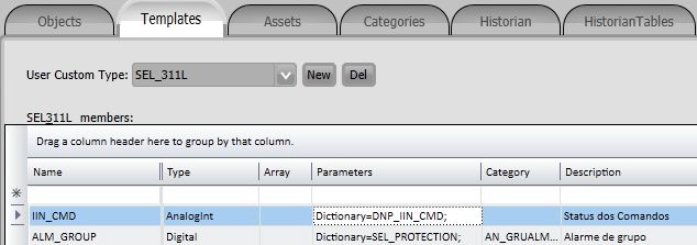
Note
For an event to always occur in this tag, the communication module always sets the value as 99 in the tag before starting to send a command. Afterwards, it puts in the tag the result obtained from the response to the command.
The Address field to be filled when registering a point is what the standard calls “Index.” It consists of a 16-bit number that is the indicative index [0 to n-1] of each of the points of the same type mapped within the IED.
For example purposes, a points table filled with several types of points is presented below. The digital output type points (CRO), as mentioned above, have their control code, besides the address.
To implement discrete digital input points, it is enough to use the “Bit” attribute of a tag for each of the points that define the discrete digital input value. Therefore, for example, a switch with two contacts that define its state:
| Tag | Address | Complement |
|---|---|---|
| SEL_LINHA_01.SC89_1 | 8 | Switch Open |
| SEL_LINHA_01.SC89_1 | 9 | Switch Closed |
This is defined as an AnalogInt Tag and the Bit attribute of this 16-bit variable (AnalogInt) is used on the node table to address two points, as in the figure below:
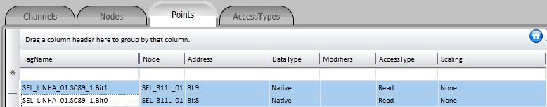
The values assumed by the SEL_LINHA_01.SC89_1 variable will be:
| Tag | Bit 0 | Bit 1 | Value | Meaning |
|---|---|---|---|---|
| SEL_LINHA_01.SC89_1 | 0 | 0 | 0 | UNDEFINED |
| SEL_LINHA_01.SC89_1 | 1 | 0 | 1 | OPEN |
| SEL_LINHA_01.SC89_1 | 0 | 1 | 2 | CLOSED |
| SEL_LINHA_01.SC89_1 | 1 | 1 | 3 | ERROR |
Since this is a communication module in client mode, it requires a few characteristics of its own for parametrization of the Access Type field in the Points table:
For reading-type points, the Access Type must be defined as:
For command-type points (CRO, AO and AOL), the Access Type must be defined as: