Page Tree
Previous Releases
The devices in FactoryStudio are any live real-time data source. Typically, a device is a PLC, another FactoryStudio project, an OPC server, a PI System, or any other equipment that has a communication protocol.
Data sources are connected to FactoryStudio through Channels. Each channel has an interface type (e.g. RS-232, TCP/IP) and a device-specific protocol. A channel may access multiple stations (e.g. devices) using a common protocol.
Each stations is called a Node. Each node has one or more data Points. Data points provide the specific data values for tags to access. Each data point is bound to a specific tag.
Finally, each data point is associated with an Access Type. This defines the rules for reading and writing values for this data point, such as the polling rate, whether a read is performed on startup, and whether unsolicited input is accepted.
In Summary, the Device Module configuration is executed in 3 steps:
1) Define the equipment and protocols the project will use, in Edit → Devices → Channels.
2) Defined the Nodes or the PLC stations related to each channel, in Edit → Devices → Nodes
3) Map the tags in the data model to addresses in the devices, in Edit → Devices → Points.
Optionally, you can customize or create new AccessTypes by mapping groups of tags, that similar communication requirements, to the same AccessType.
In order to expedite the configuration, FactoryStudio provides many Import Wizards that automatically create the Tag and Device mapping using the PLC configuration or another available source of information. Link to current list of Import Wizards.
Channels in FactoryStudio are the protocols you use to communicate with your PLCs. Many built-in protocols are available. You must set up a channel for each protocol you need to use.
To configure channels:
Enter or select information, as needed.
Column | Description |
Channel Name | Enter a name for the channel. The system lets you know if the name is not valid. |
Protocol | Select the protocol this channel uses. |
Interface | Select the interface type for this channel.
|
Description | Enter a description for this channel. For more information about the configuration for common protocols and interfaces, click Help at the top of the tab.| |
To add or remove a column, right-click the column heading area and select or deselect columns.
Column | Description |
ProtocolOptions | Configure the options for this protocol. |
Settings | Configure the settings for this channel. The available values depend on the interface the channel is using. The settings here must match the settings on the slave device.
|
Timeout | Configure the timeout options for this channel. Typically, keep the default value. |
IntialState | Select the initial state for this channel. |
Remote Settings | Set the primary IP and backup IP to configure the server addresses for this device module |
Driver Version | The version of the current driver being used. |
| [Other columns] | For definitions of other columns that are available in many tables, see Common Column Definitions. |
Connectivity is a key feature of the FactoryStudio platform. The system has built-in support for many industry standard protocols, such as OPC and Modbus. FactoryStudio also includes many native communication interfaces for a variety of hardware manufacturers, PLC, and protocols.
There are many reasons for including native protocols as well as OPCs:
Tatsoft is continuously adding new communication drivers.
Nodes in FactoryStudio are the devices or PLCs on the network that you communicate with.
You can enter the settings for your nodes as usual through the Engineering Workspace. You can also import settings from an OPC server or from another data source. See "Importing PLC Addresses" below.
To configure nodes:
To add or remove a column, right-click the column heading area and select or deselect columns.
Column | Description |
Name | Enter a name for the node. The system lets you know if the name is not valid. |
Channel | Select the channel for this node. For more information about the configuration for common protocols, click Help at the top of the tab. |
PrimaryStation | Enter the information required to access the primary node, based on the protocol selected. The protocol options are dependent upon the selected protocol. Select the protocol from the dropdown list at the top of the page and press the HELP button to access the specific protocol's documentation. For Modbus protocol:
OPC UA and OPCXmlDA protocols have a "Test"button to test the connection. OPC UA also has a "Certificates" button to create new certificates for the system.| |
BackupStation | Enter the information required, based on the protocol, to access the backup node. When the backupstation is defined and a communication failure occurs on the primary station, the system automatically attempts to establish communication with the backup station. |
SyncDate | Date that the import was done (read only field) |
SyncStation | Information about the station where the import was done - Station IP, Port and Slot - (read only field) |
SyncSettings | Information about the settings used by the system to import the file (read only field) |
Description | Enter a description for this node. |
| [Other columns] | For definitions of other columns that are available in many tables, see Common Column Definitions. |
Data points define specific values for each node that can be accessed using tags. The number of data points you can configure is related to both the ProductModel that is configured for the project and your FactoryStudio license.
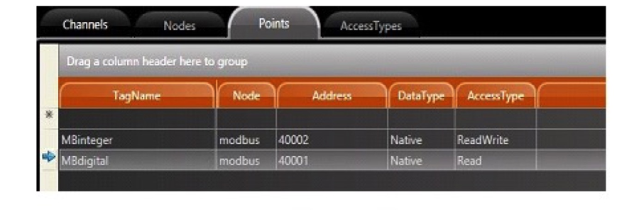
To configure data points:
To add or remove a column, right-click the column heading area and select or deselect columns.
Column | Description |
TagName | Enter a tag name or click ... to select a tag. You can also create a new tag. |
Node | Select the node for this data point. |
Address | Enter the register address which is based on the PLC and protocol for this data point and tag. The Protocol options are dependent upon which protocol is selected. Select the protocol from the dropdown list at the top of the page, and press the HELP button to access the specific protocol's documentation. |
DataType | Select the data type you want to use. Most protocols should use the native option. When native is used, the protocol will automatically handle the data conversion. Selecting a different data type overrides the defaults. Some options may not be applicable to the selected node. Make sure you know the applicable data types. |
Modifiers | If the PLC uses a different byte order, select the options you want. You can change the position bit, byte, Word, or Dword of the data that is communicated. |
AccessType | Select the access type for this data point. You can define and configure the access types. See Access Types, below. |
Scaling | If you want to manipulate the tag value, select the options you want. When the data is read in the Equation option:
|
| Label | A text that represents a label on the point |
| [Other columns] | For definitions of other columns that are available in many tables, see Common Column Definitions. |
Access types define the specific methods for reading and writing the values of each data point. This could be the polling rate, whether or not a read is performed on startup, and whether or not unsolicited input is accepted. FactoryStudio comes with a few predefined access types that you can use, or you can create your own.
To configure access types:
Enter or select information, as needed.
Column | Description |
Name | Enter a name for this access type. |
Read | |
ReadPolling | Select when you want to enable read polling. |
ReadPollingRate | Enter how often the address value is retrieved. |
ReadTrigger | Enter an object property that tells the system when to read the value. |
ReadOnStartup | When selected, the system reads the value on startup. |
ReadStatus | Enter an object property that receives the status of the read communication. |
ReadCompleted | Enter an object property that receives an indication that the reading is completed. The value will change between 0 and 1 every time a reading is completed. |
Write | |
WriteEventEnable | Select to enable the writing of values to the PLC. |
WriteEvent | Select when the value is written. |
WriteTrigger | Enter an object property that tells the system when to write the value. |
WriteStatus | Enter an object property that receives the status of the write communication. |
WriteCompleted | Enter an object property that receives an indication that the writing is completed. The value will change between 0 and 1 every time a writing is completed. |
Settings | |
AcceptUnsolicited | When selected, the system accepts values from the PLC, even if the polling time has not yet elapsed. |
UseStaticBlocks | Select to use the block command field |
BlockCommand | Enter a definition for each block that will be created. Check the driver documentation to see if the specific driver uses this field and the valid values. |
Description | Enter a description for the access type. |
[Other columns] | For definitions of other columns that are available in many tables, see Common Column Definitions. |
Communication nodes and data points that have been defined by another data source can be imported in the following ways:
If your PLC or field device has an open database or a file with available addresses and you want the PLC and FactoryStudio addresses to have tight integration, contact support.
Importing from an OPC Server
After you create an OPC communication node, you can select the node and click Import to import the OPC database for the project. FactoryStudio automatically creates the tags and communication points.
Importing from Excel
To create and import Tags:
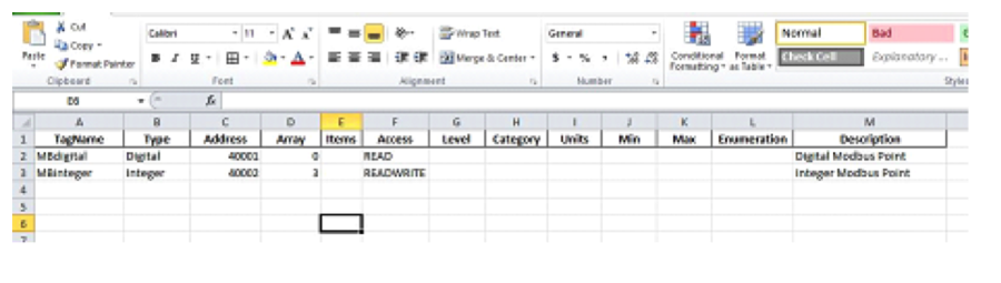
To successfully import the tags, you need the TagName, Type, and Address columns.
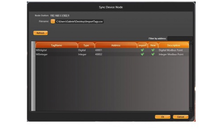
After you use the Import tool for the first time, the system will save whatever settings you used. The import button switches to now be called the "Sync" button. This make the button execute a synchronization that verifies the previously imported addresses and the new ones.
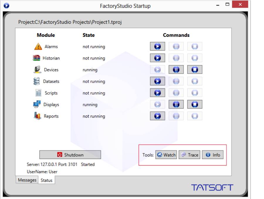
After you start the project in the Startup window, select the diagnostic tools. These are: PropertyWatch (Watch), TraceWindow (Trace), and ModuleInformation (Info).
You can also start the diagnostic tools on the Run-Test and Run-Startup pages by clicking on the desired tool's icon with the lift mouse button. If menus are enabled for the display, you can also access the tools menu.
Module Information
The Module Information tool provides information about the operation of the modules. If you choose the devices module and a specific channel, you will see information regarding the function of the communication channel.
The "Read Groups Information" is important because it provides information about the virtual reading groups, the run time of each item, the quantity of the readings, and the readings that have failed. It also reports on the code and date/time of the last error.
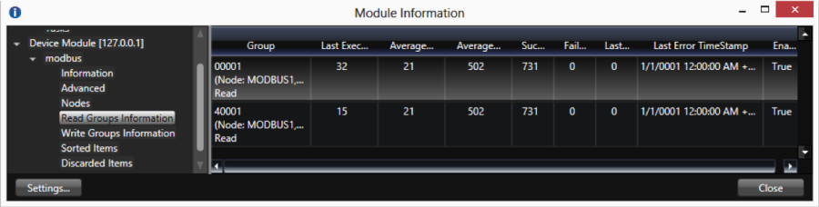
These are the typical steps to use the Module Information tool:
Keep in mind that you can only READ from a field device when an Enterprise application is running in test mode. This makes it useful to run the application with ONLINE CONFIGURATION enabled because you do not need to start and stop the driver when modifying the configuration. You can modify PLC addresses, AccessTypes, and most of the application, and you can see the results in real-time on your running application. You can use the Startup window or the PropertyWatch tool to start and stop only one module, instead of restarting the entire runtime system.
Property Watch
Property Watch is a diagnostic tool used to access the tags and internal properties of the system for reading or writing. Type the name of the property in the Object column, and its value will be found in the Value column.
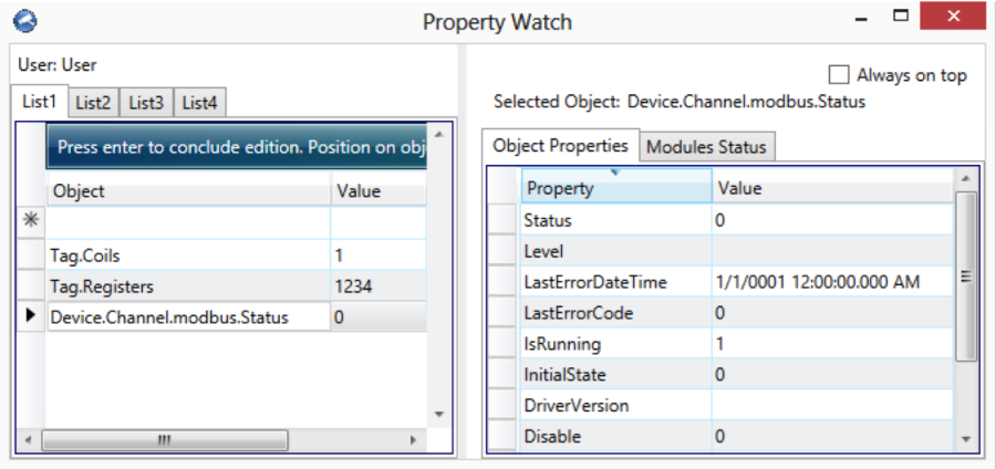
For example, in the screen shown above, select Tag.Coils or Device.Channel.modbus.Status . The value of these objects will be shown. To the right side, additional properties are displayed for the selected object.
Devices negative error code
Trace Window
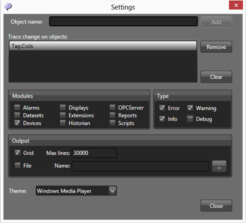
The Trace Window tool displays system messages in a data grid interface. If you enable the module devices in the settings, information will be available about the status of reads, writes, unsolicited input, TX frames (sent), and RX frames (received).
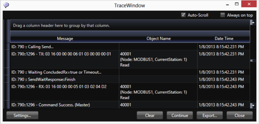
When checking the devices CheckBox in the Settings, enable only the ERROR, INFO, and Warning information. Do not enable the Debug information, or you will create too much data. For ControlLogix devices, it is very important to use this tool, as the system will present here the invalid addresses on the configuration.
If you click on the settings button in the configuration dialog, you can select which message types and modules to display. You can see the data in the data grid or save it to a file. It is also possible to configure a tag in ObjectName, and click the Add button to display a menu to select that object and include it in the monitoring.
For more information on how to use the Diagnostic Tools, please see Using the Diagnostic Tools.
The Device namespace is the entry point for all objects related to the device module.
The Device.Channel object lists all of the configured channels and their runtime properties.
The Device.Node object lists all of the configured nodes and their runtime properties.
The Device.AccessType object lists the defined access types and has options to execute synchronous calls on reading and writing to the device.
The following tag properties are updated based on the device module:
tag.tagname.DevicePoint: Device point address connected with this tag
See Namespaces for the complete programming reference on runtime objects.