Page Tree
Previous Releases
IEC861850 Scada Client implements the part of the standard IEC61850 responsible for ACSI core services, as defined in part 8.1 of IEC861850 standard. It uses encapsulation of the ISO/OSI transport layer into the TCP/IP transport layer. It communicates with IEDs (Intelligent Electronic Devices), RTUs (Remote Terminal Units) and IO devices that support this protocol, acting as the client workstation.
Communication Driver Name : IEC 61850 Client Communication Protocol
Current Version : 2016.2 – 1.3
Implementation DLL : T.ProtocolDriver. IEC61850.dll
Protocol : IEC-61850 Client communication protocol - Edition 2
Interface : TCP/IP
Protocol Options : Timers for protocol control messages
Max number of nodes : User defined
PC Hardware requirements : Standard PC Ethernet interface board
Note
This communication module was rewritten for version an-2016.2 , and uses a library that is different from the one previously used. Changes were made to the configuration procedures of channels, nodes and points. The following section provides notes to aid in the migration of projects that were already using the module from the previous version.
Scada users of communication module - Issue 1 need to update the channel registration,
nodes, and project points. Below are the steps for migrating existing projects to the new
issue.
1. Copy all points referring to the nodes of Project Communication Module 61850 to an
Excel worksheet.
2. Delete all points referring to the nodes of Project Communication Module 61850.
3. Copy the names of the project nodes and channels to the notebook.
4. Delete all nodes.
5. Delete all channels.
6. Create the channels with the names previously copied in step 3. Configuring each
channel according to session 2 - CHANNEL CONFIG – Does not allow copy and paste.
7. Create the nodes with the names previously copied in step 3. Configuring each node
according to session 3 - CONFIGURING US (NODE CONFIG) – Does not allow copy and
paste.
8. Paste the point definitions previously copied in step 1.
9. When starting the Communication Module, all the Point entries will be validated. If
point mistakes occur, they will be recorded in the Log (See section 7.1 - Logs of
operations (LOG)) and check how to correct them in session 4 - CONFIGURATION
OF POINTS (POINTS CONFIG ).
This section aims to briefly present some information on the standard IEC 61850, which
directly interferes in the definition and implementation of this communication module.
For more details and a formal description, refer to the standard’s texts or documentation of
the server IEDs.
The standard is divided into ten parts, listed below.
Chapter Description
1. Introduction and Overview
2. Glossary
3. General Requirements
4. System and Project Management
5. Communication Requirements for Device Functions and Models
6. Configuration of the Description Language for Communication in Substations with
IEDs
7. Basic Communication Structures for Substations and Feeders: Principles and Models
7.2 Basic Communication Structures for Substations and Feeders:
7.3 Basic Communication Structures for Substations and Feeders: Common Data Class
7.4 Basic Communication Structures for Substations and Feeds: Classes of Logic Nodes
and Compatible Data
8. Mapping for MMS (ISO/IEC 9506-1 and ISO/IEC 9506-2) and for ISO/IEC8802-3
9.1 Sample Values on One-way Multidrop Point-to-point
9.2 Sample Values for ISO/IEC8802-3
10 Conformity Tests
As regards the support for data communication between computers and IEDs, as
established by the standard, the types of messages defined are listed below.
Message Description
GOOSE Generic Object Oriented Substation - Multicast-type messages that load
information between IEDs. They are responsible only for the traffic of messages about the
performance of any protection or digital signal.
MMS Manufacturing Message Specification - Unicast-type messages that are used to
exchange analog or digital (state) measurement data to indicate the state of the equipment
and process.
One of the great advantages introduced by the standard in defining its data communication
protocol is the fact that the internal points to an IED do not use numbers for addresses , as
in other protocols, but names instead. Each point is considered an object, and its names
and formats are standardized by the norm.
Internally to the IEC61850 IEDs there is a map of the objects , arranged in a hierarchical
structure. In the communication between a client (for example, SCADA) and the server (for
example, a digital-IED relay), these object names (at least when communication is initially
established) travel in the protocol messages.
In order to have a general idea of these object’s names, the next section briefly presents the
structure of the address map hierarchy of the IEC61850.
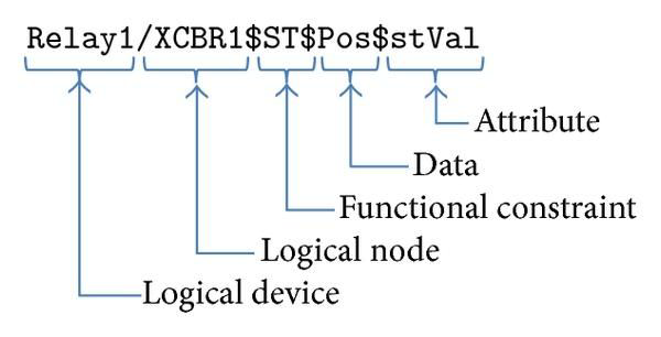
LD - Logical Devices - These are logical devices within this physical server, which work as
function containers (Logical Nodes) or even as gateways between different LD LNs.
Generally, IED internal names are used in the initial part of the name (prefixes) and suffixes
that indicate the main function of the LD. Examples of suffixes are CTRL, MEAS, etc.
LN - Logical Nodes - Objects that implement the well-defined basic functions within the
Logical Device. The names of Logical Nodes are standardized. Each LN contains objects,
data sets, Report definitions, Logs, parameter groups, and services that implement objects
and functions. For example, a disconnect switch, its state, its control, has the name
“Q0CSWI1.” The LN in this case is the CSWI – “Switch controller.” Other examples of LNs
would be those that perform measurement functions (MMXU), voltage transformer (TVTR),
overcurrent protection (PTOC), thermal protection (PTTR). A complete list of LNs for use in
substation IEDs and the rules for forming their names are given in IEC61850-Part 5.
FC - Functional Constraints - The function defined by the LN will contain several objects
that are distributed in categories defined as FC-Functional Constraints. These are “CO” that
will contain command objects, “ST” that will contain digital signaling objects, “RP” for
report-type objects, and “MX” for measurement objects. The list of the following FCs was
obtained from IEC61850 Part 7-2-2003 - Table 18. More details about each item can be
found in the original table.
ST Status information
| Term | Description |
|---|---|
| MX | Measurements (analog values) |
| CO | Control DataAttribute will be operated (control model) and read |
| SP | Setpoint DataAttribute will represent a set-point; value may be controlled and read |
| SV | Substitution DataAttribute will represent a substitution |
| CF | Configuration DataAttribute will represent a configuration |
| DC | Description DataAttribute will represent a description |
| SG | Setting group logical devices that implement the SGCB class |
| SE | Setting group |
| EX | Extended definition |
| BR | Buffered report |
| RP | Unbuffered report |
| LG | Logging Attribute will represent a log control |
| GO | Goose control |
| GS | Gsse control Attribute will represent a goose control |
| MS | Multicast sampled value control |
| US | Unicast sampled value control |
DO - Data objects - Data Objects are objects with standard names that contain the
information proper. These objects can be simple, such as the “Pos” object, which provides
information on the circuit breaker position. There are more complex “A” objects, which
represent a three-phase current. It is made up of four Data Attributes, each of which
containing Child Data Attributes with the current information about each phase and a
neutral. It has in the latter case multiple levels of Data Attributes in the hierarchy below a
Data Object.
Examples of DataObjects are:
Beh - Behavior of LN
Health - State of the logical node related to HW and SW.
Loc - Switchover between local and remote operation
Mod - Mode and behavior: On, Blocked, Test, Test/Blocked, Off
Pos - Switch position
A - Current
neut - Phase neutral
phsA, phsB, PhsC - Phases A, B and C
Hz - Frequency
PPV - Phase to phase voltages
PhV - Phase to ground voltages for Phases 1, 2, and 3, including Angle
DA - Data Attributes - Each object hierarchically below a Data Object or another Data
Attribute, in the case of “ctlNum” or a phase of the stream as “phsC.” Examples:
In the case of “Pos” you can see four Data Attributes:
stVal - Containing the state of the circuit breaker
q - The quality of the data
t - Sampling timestamp
ctlNum - Data object status change sequence number
In the case of the current “pshC,” besides being a Data Attribute itself, it also contains four
Data Attributes below it:
cVal - The current measurement
instCval - The instantaneous measure of the current at the last acquisition
q - The quality of the data
t - Sampling timestamp.
For the end user, the way services are used is transparent. They are only required to know
how to set up the user-friendly configuration interfaces for running the IEC61850 SCADA
Client.
The communication module consists of two libraries that work together: Communication
and Integration.
The communication library is developed in the C ++ programming language and is
responsible for the communication between the Communication Module and the
equipment. It is designed according to edition 2 of the IEC 61850 standard series.
The following table provides an overview of supported IEC 61850 objects.
| IEC 61850 Objects | MMS Object |
|---|---|
| SERVER class | Virtual Manufacturing Device (VMD) |
| LOGICAL DEVICE class | Domain |
| LOGICAL NODE class | Named Variable |
| DATA class | Named Variable |
| DATA-SET class | Named Variable List |
| SETTING-GROUP-CONTROL-BLOCK class | Named Variable |
| REPORT-CONTROL-BLOCK class | Named Variable |
| LOG class | Journal |
| LOG-CONTROL-BLOCK class | Named Variable |
| GOOSE-CONTROL-BLOCK class | Named Variable |
| GSSE-CONTROL-BLOCK class | Named Variable |
| CONTROL class | Named Variable |
| Files | Files |
The following table provides an overview of supported IEC 61850 Abstract Communication
Service Interface (ACSI) services.
| IEC 61850 Model | IEC 61850 Services | AA: TP/M C | Client | Server | |
|---|---|---|---|---|---|
| Server | S1 | ServerDirectory | TP | Yes | Yes |
| Application association | S2 | Associate | TP | Yes | Yes |
| S3 | Abort | TP | Yes | Yes | |
| S4 | Release | TP | Yes | Yes | |
| Logical device | S5 | LogicalDeviceDirectory | TP | Yes | Yes |
| Logical node | S6 | LogicalNodeDirectory | TP | Yes | Yes |
| S7 | GetAllDataValues | TP | Yes | Yes | |
| Data set | S12 | GetDataSetValues | TP | Yes | Yes |
| S13 | SetDataSetValues | TP | Yes | Yes | |
| S14 | CreateDataSet | TP | Yes | Yes | |
| S15 | DeleteDataSet | TP | Yes | Yes | |
| S16 | GetDataSetDirectory | TP | Yes | Yes | |
| Substitution | S17 | SetDataValues | TP | Yes | Yes |
| Setting group control block | S18 | SelectActiveSG | TP | Yes | Yes |
| S19 | SelectEditSG | TP | Yes | Yes | |
| S20 | SetSGValues | TP | Yes | Yes | |
| S21 | ConfirmEditSGValues | TP | Yes | Yes | |
| S22 | GetSGValues | TP | Yes | Yes | |
| S23 | GetSGCBValues | TP | Yes | Yes | |
| Buffered report control block (BRCB) | S24 | Report | TP | Yes | Yes |
| S24-1 | data-change (dchg) | TP | Yes | Yes | |
| S24-2 | qchg-change (qchg) | TP | Yes | Yes | |
| S24-3 | data-update (dupd) | TP | Yes | Yes | |
| S25 | GetBRCBValues | TP | Yes | Yes | |
| S26 | SetBRCBValues | TP | Yes | Yes | |
| Unbuffered report control block (URCB) | S27 | Report | TP | Yes | Yes |
| S27-1 | data-change (dchg) | TP | Yes | Yes | |
| S27-2 | qchg-change (qchg) | TP | Yes | Yes | |
| S27-3 | data-update (dupd) | TP | Yes | Yes | |
| S28 | GetURCBValues | TP | Yes | Yes | |
| S29 | SetURCBValues | TP | Yes | Yes | |
| Log control block | S30 | GetLCBValues | TP | Yes | Yes |
| S31 | SetLCBValues | TP | Yes | Yes | |
| S32 | QueryLogByTime | TP | Yes | Yes | |
| S33 | QueryLogAfter | TP | Yes | Yes | |
| S34 | GetLogStatusValues | TP | Yes | Yes | |
| GOOSE control block | S35 | SendGOOSEMessage | MC | Yes | Yes |
| S36 | GetGoReference | TP | |||
| S37 | GetGOOSEElementNu mber | TP | |||
| S38 | GetGoCBValues | TP | Yes | Yes | |
| S39 | SetGoCBValues | TP | Yes | Yes | |
| GSSE control block | S40 | SendGSSEMessage | MC | ||
| S41 | GetGsReference | TP | |||
| S42 | GetGSSEElementNum ber | TP | |||
| S43 | GetGsCBValues | TP | |||
| S44 | SetGsCBValues | TP | |||
| Multicast SVC | S45 | SendMSVMessage | MC | Yes | |
| S46 | GetMSVCBValues | TP | Yes | Yes | |
| S47 | SetMSVCBValues | TP | Yes | Yes | |
| Unicast SVC | S48 | SendUSVMessage | TP | Yes | |
| S49 | GetUSVCBValues | TP | Yes | Yes | |
| S50 | SetUSVCBValues | TP | Yes | Yes | |
| Control | S51 | Select | TP | Yes | Yes |
| S52 | SelectWithValue | TP | Yes | Yes | |
| S53 | Cancel | TP | Yes | Yes | |
| S54 | Operate | TP | Yes | Yes | |
| S55 | Command-Termination | TP | Yes | Yes | |
| S56 | TimeActivated-Operate | TP | Yes | Yes | |
| File transfer | S57 | GetFile | TP | Yes | Yes |
| S58 | SetFile | TP | Yes | Yes | |
| S59 | DeleteFile | TP | Yes | Yes | |
| S60 | GetFileAttributeValues | TP | Yes | Yes | |
| Time | T1 | Time resolution of internal clock | 1ms | 1ms | |
| T2 | Time accuracy of internal clock | ||||
| T3 | Supported Timestamp resolution | 1ms | 1ms | ||
| AA – Application association | |||||
Legend: TP – Two-party application association (MMS over TCP/IP or Unicast Sampled Value on top | |||||
The integration library is developed in the C # programming language and is responsible for
the integration between the Communication Module and SCADA. It aims to transact the
read and write information between the device and SCADA.
The following table provides an overview of implemented IEC 61850 objects. The fields
marked with a (?) indicate the implementation of the service.
| IEC 61850 Objects | |
|---|---|
| SERVER class | |
| LOGICAL DEVICE class | Yes |
| LOGICAL NODE class | Yes |
| DATA class | Yes |
| DATA-SET class | Yes |
| SETTING-GROUP-CONTROL-BLOCK class | |
| REPORT-CONTROL-BLOCK class | Yes |
| LOG class | |
| LOG-CONTROL-BLOCK class | |
| GOOSE-CONTROL-BLOCK class | |
| GSSE-CONTROL-BLOCK class | |
| CONTROL class | Yes |
| Files | |
The following table provides an overview of the implemented IEC 61850 Abstract
Communication Service Interface (ACSI) services. The fields marked with a (?) indicate the
implementation of the service.
It's essential to link from one page to another and to specific sections on a page. You can add any URL to a Confluence page and Confluence will automatically detect it and turn it into a link.
If you paste the URL for another page in your Confluence site, Confluence will display the link text as the page name and turn it into a relative link, meaning if the name of the page changes, Confluence will adjust the link so it doesn't break.
The anchor macro allows you to create anchors in your documentation, which can be linked to or from anywhere.
To add a macro and link to it from the same page:
{anchor in the editor, select the anchor macro and give your anchor a nameCtrl+K (Windows) or Cmd+K (Mac) (this opens the link dialog)# followed by your anchor nameCheck the Confluence documentation for more information on how to use links and anchors.
If you want to anchor or link, make sure you correctly anchor or link to another page or to a specific line of the document. Add the anchor immediately above the corresponding section title and/or link to the correct word or section.
Be sure when adding images that they are very clear, especially if they contain text, and try to only capture a close up of the important thing you are referencing. You may need to overlay a few screenshots depending on what you are doing. If you need help capturing what you need ask for assistance as a different capture tool may help immensely.
Use the "Insert files and images" tool at the top to insert an image.
Then, be sure to click the "Original" button, and the "Border" button. The Original button will ensure the image is sized as the original, which should have be large enough to read clearly. If needed, you can adjust the size after that, but larger is okay if it helps clarity. The border button will put a box around the image to help delineate it from the white background, which is really useful on some screen shots that also have a lot of white on the edge.
Use macros when needed to help draw attention to particular information. Here's a few:
Often when creating documentation, there are elements of a page that you want to highlight or draw the the viewers' attention to. Confluence ships with the Tip, Info, Warning, Note and Panel macros, which will help you focus a viewer's attention on a particular part of your content.
| Term | Description |
|---|---|