Page Tree
Previous Releases
The SCADA IEC870504 protocol driver implements comunication with IEDs (Intelligent Eletronic Devices), RTUs (Remote Terminal Units) and IO devices compatible with this protocol, acting as a master station.
Communication Driver Name: IEC8705104
Current Version: 2016.2
Implementation DLL: T.ProtocolDriver.IEC8705104.dll
Protocol: IEC-60870-5-104 Master standard protocol
Interface: TCP/IP
IEDs types supported: Any IED compatible with IEC-60870-5-104.
Communication block size: Maximum 253 bytes
Protocol Options: Counters for sending protocol control messages.
Multi-threading: User defined, five threads per node by default.
Max number of nodes: User defined
PC Hardware requirements: Standard PC Ethernet interface board
The protocol uses the same ASDUs defined for IEC-60870-5-101 as well as the same types of data objects. The major difference is that it’s targeted only towards network uses, with TCP/IP as the transport layer instead of serial communication.
It also uses all the 56-bit timestamp variants of the above ASDUs. The codes above are used when registering points, but if the slave IED sends variants with date and timestamp, the measures and states received will be placed on the quality and timestamp attributes of the correspondent points.
The IEC-60870-5-104 protocol is implemented in Master mode in which it communicates with IEDs that implement the slave IEC-870-5-104 protocol. Various parameterizations are available to accommodate different profiles of protocol implementations.
The Master has the following operating sequence:
On start or communication failure:
On an infinity loop:
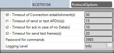
t0 - Timeout of Connection establishment(s) – Maximum acceptable time, in seconds, for a TCP/IP connection attempt to a remote IED. After this time, the driver closes connection and attempts another connection. Values from 1 to 255 are allowed.
t1 - Timeout of send or test APDUs(s) – Maximum waiting time, in seconds, for sending a regular APDU or testing APDU after a START DT confirmation is received. Values from 1 to 255 are allowed.
t2 - Timeout for ack in case of no data(s) – Maximum waiting time, in seconds, for a pending acknowledgement before sending an acknowledgement for the last received message. A message will be sent with the sequence number of the last one received. Values from 1 to 255 are allowed. The t2 time must be shorter than t1.
t3 - Timeout for send test frames(s) – Maximum waiting time, in seconds, for the arrival of any information (in case of a TCP-IP connection is already established) before sending a TEST-FR. Values allowed are from 1 to 255.
Password for commands: To increase the security of sending commands, normally initiated only by a change in the state of a tag, it is possible here to specify a password of up to nine digits. The communication module will verify, at the moment the command is received, this password against the current value of the EstimatedValue attribute tag involved in the command. Therefore, in the operation of sending a command through a window, script, etc. this number must be loaded in this attribute. The communication module, after executing the command, changes the value of EstimatedValue to ZERO. This verification does not occur if this option is left as zero.
Logging Level – You can choose from this list the logging mode created by the communication module.
| Logging Level | |
|---|---|
| Debug | All messages are registered in the LOG |
| Info | Only Info, Warning and Error messages are registered in the LOG |
| Warning | Only Warning and Error messages are registered in the LOG |
| Error | Only Error messages are registered in the LOG |
The figure below shows the filling of these fields in the channel:
TCP/IP channels:
Each node is a server station (IED). User may set a single station per channel.
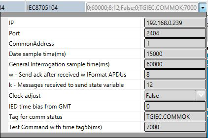
IP Address – IED’s IP address must be specified
Port – Number of port to be used. The standard defines port 2404, by default. User can use custom port numbers
CommonAddress - Application layer address
Date sample time – Period of time, in milliseconds, between two consecutive submissions of Date and Time for remote IED synchronization, if necessary. Zero is used to indicate that there is no need for synchronization. Note that the master should not synchronize IEDs synchronized by GPS.
General Interrogation (GI) sample time – Period of time, in milliseconds, between two consecutive submissions of general interrogation requests to an IED. The IED responds by sending blocks of information, as many as are required to send all points.
w – Send ack after received w IFormatAPDUs – Number of information messages received spontaneously before sending an “acknowledgment” with the sequence number of last message received. The allowed values are between 1 and 32767.
k – Messages received to send state variable – Maximum allowed number of pending acknowledgements before slave stops sending new messages. It is recommended that w be at most two-thirds of the k value. Values between 1 and 32767 are allowed.
Clock Adjust – Can be set as “True” to adjust the clock on this server computer or “False” to make no adjustment. The module makes the adjustment by changing the machine time to match the one that came as the answer to a synchronization message sent. For this to be effective, the slave IED must answer with a time that comes, for example, from a GPS.
IED time bias from GMT - On SCADA, internally, all timestamps are stored with GMT (UTC) dates. IEDs usually send these dates also in GMT and no adjustment is required. The default for this option is zero. If in the current implementation the IEDs send the timestamps in their local time, the difference between this time and GMT time must be specified in this field. For example, in New York, the local time is 4 hours less than GMT. In this case, -4 should be specified in this table.
Tag for Comm status - In this field the name of an existing tag in the project can be indicated to show success/failure in communication from a functional point of view. When making requests, the module waits for a maximum of t2 seconds (defined in Protocol Options, above) to receive a response. In case of failure, the system sets the value of this tag to ZERO. In case of success, the system sets the value in this tag to ONE.
Test Command with Time tag56 (ms) - Period of time in milliseconds between two consecutive submissions of an ASDU Test Command with a CP56 timetag, if necessary. Zero is used to indicate that there is no need for this test. This test facilitates for the server side to detect communication failures, and also serves to remove unsolicited messages received by the master.
The figure below shows the filling of these fields for the main station:
Backup Station – The same communications settings adjusted to an IED can be adjusted to a backup workstation (alternative IED) if there is one in the facility.
Points can be input or output points. Input points, i.e. points that are acquired by the protocol, have basically two main parameters: point type and address. Output points are used for remote controls, and have an additional address parameter to specify an output operation. In a given IED, addresses are unique no matter what kind of point.
The SCADA master mode implements:
The point types were implemented as their respective ASDUs objects defined in the standard (see list below).
M_SP_NA: 1 - Single-point information
M_DP_NA: 3 - Double-point information
M_ST_NA: 5 - Step position
M_BO_NA: 7 - Bitstring with 32 bits
M_ME_NA: 9 - Measured value, normalized
M_ME_NB: 11 - Measured value, scaled value
M_ME_NC: 13 - Measured value short floating point
M_IT_NA: 15 - Integrated totals
C_SC_NA: 45 - Single command
C_DC_NA: 46 - Double command
C_RC_NA: 47 - Regulating step command
C_SE_NA: 48 - Set point command, normalized value
C_SE_NC: 50 - Set point command, short floating point value
C_BO_NA: 51- Write Bitstring de 32 bits
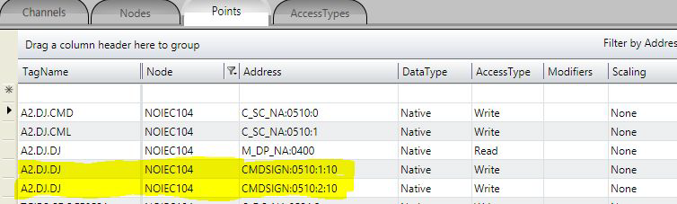
CMDSIGN - Command Signaling
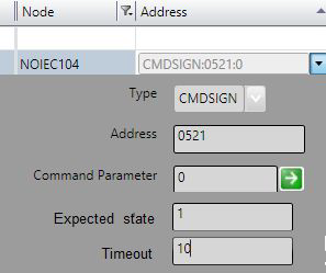
The following figure shows the setting in the POINTS table. The signaling comes in tag A2.DJ.DJ, of type M_DP_NA. The two lines highlighted in yellow show definition of the signaling of commands with the same address (0510) and control code (0 - Open and 1 - Close).
The protocol module uses these two lines to create a static list with all matches on the node. Their information does not create new points in real time.
Nothing else is required for setup. With this list the module will automatically call the transaction creation and verification methods.
This Command Signaling feature can be used only for C_SC_NA and C_DC_NA digital commands and M_DP_NA and M_SP_NA digital signals.
The completion of point addresses is done in the engineering environment, in Edit> Devices> Points.
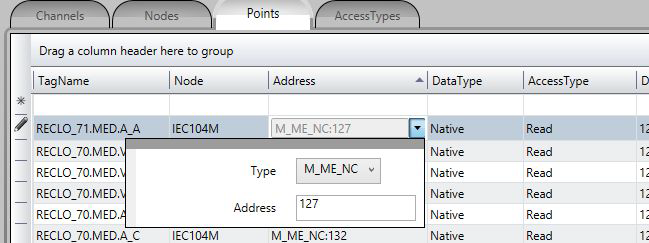
The Address field to be filled in when registering a point is what the standard calls the “Information Object Address.” This is a 3-byte number that does not repeat for a given IED (node), the address being assigned by the IED manufacturer.
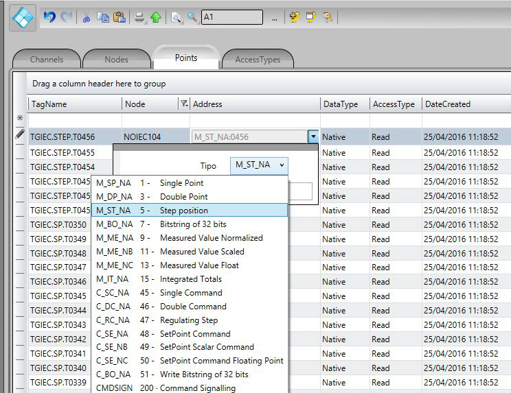
As shown in the figure below, a click on the row of the address column opens a window to select the type and address of the point. A click on the type opens a window with all types of points supported:
To select Type:
The command parameter is a one-byte code which details what and how the server IED should execute the command. In this implementation, as the user registers a point typed as command output, this field shows up to receive this code. If the user knows the code, then he or she can just type it in the field. Otherwise, they must click on the button to the right of field for displaying the window with the actions and details available.
The codes generated by choosing the items in the window parameter setting command are formed by calculating the sum of two parts (A and B), where the first part indicates the action, and the second the details of the transaction, as defined below:
For Single Command C_SC_NA:
For Double Command C_DC_NA:
For Voltage Regulation C_RC_NA:
The remaining options are the Select type command - just select the device to be controlled; or the Execute type command - send the proper action command. In case the Select command is chosen, add 128 to the code obtained from the sum of the parts A and B.
Example: code = 9 in a simple command means Long Pulse for Turn on the remote device.
In order to set up the SCADA with output parameters, follow the procedure below:
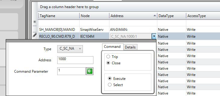
(1) Click the right border of the address once to show three command parameters in the command tab:
And the command options:
(2) Select the desired options and by clicking on the left arrow ( ), the binary value corresponding to the selection will be loaded in the command parameter:
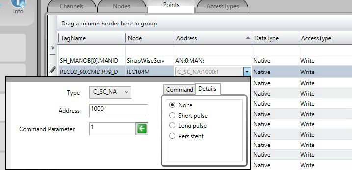
(3) If detailing the type of signal to be sent is necessary, before clicking on the left arrow click on details and, as in the figure below, select the type of the output signal:
Since this is a communication module in master mode (server), it requires a few specific characteristics of its own in order to parameterize the Access Type field in the Points table:
For reading-type points:
The Access Type must be defined with:
For command-type commands:
The Access Type must be defined with: