Page Tree
Previous Releases
For a generic explanation on Device Module, Channels, Nodes, and Points configuration, please refer to the reference guide.
Communication Driver Name: TSimulator - SCADA Random Values
Current Version: 1.0.0.0
Implementation DLL: T.ProtocolDriver.TSimulator.dll
Protocol Options: Not used in this driver.
Node Configuration: Not used in this driver.
The syntax for the TSimulator communication points is: <Type>:<Min>;<Max>
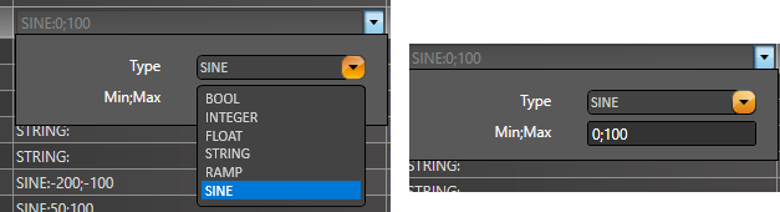
Where:
Type: Represents the Simulation Type:
For the STRING simulation type, the StringLength can be configured in the Modifiers column.
TagName | Node | Address | DataType | AccessType | Modifiers |
MySine | SimulatorNode | SINE:-50;50 | Native | Read | |
MyRamp | SimulatorNode | RAMP:0;100 | Native | Read | |
MyString | SimulatorNode | STRING: | Native | Read | StringLength=5 |
MyBool | SimulatorNode | BOOL: | Native | Read | |
MyInt | SimulatorNode | INTEGER:0;10 | Native | Read | |
MyFloat | SimulatorNode | FLOAT:-500;-100 | Native | Read |
The status of the driver execution can be observed through the diagnostic tools, which are:
Status value of 0 (zero) means communication success. Negative values indicate internal driver error and positive values mean protocol errors.