The IEC870504S protocol implements communication with client stations compatible with this protocol, acting as a slave station (server).

Summary

Communication Driver Name: IEC8705104S

Current Version: 2016.2.1

Implementation DLL: T.ProtocolDriver.IEC8705104S.dll

Protocol: IEC-60870-5-104 Slave standard protocol

Interface: TCP/IP 

Clients types supported: Any IED compatible with IEC-60870-5-104

Communication block size: Maximum 253 bytes

Protocol Options: Counters used for sending protocol control messages

Multi-threading: User defined. Five threads per node by default

Max number of nodes: User defined

PC Hardware requirements: Standard PC Ethernet interface board

Supported Objects (ASDUs)

The protocol uses the same ASDUs and object data types that are defined for IEC-60870-5-101. The major difference is that this is only targeted towards network orientation, using TCP/IP as the transport layer.

  • M_SP_NA: 1 - Single-point information
  • M_DP_NA: 3 - Double-point information
  • M_ST_NA: 5 - Step position
  • M_BO_NA: 7 - Bitstring with 32 bits
  • M_ME_NA: 9 - Measured value, normalized
  • M_ME_NB: 11 - Measured value, scaled value
  • M_ME_NC: 13 - Measured value Float
  • M_IT_NA: 15 - Integrated totals
  • C_DC_NA: 46 - Double command 
  • C_RC_NA: 47 - Regulating step command
  • C_SE_NA: 48 - Set point command, normalized value
  • C_SE_NC: 50 - Set point command, 32 bits floating point
  • C_BO_NA: 51- Write 32 bits Bitstring

Plus all the variant of the ASDUs above with a 56-bit timestamp. The above codes are used for point registration. When sending unsolicited changed, the variants with a date and timestamp obtained from the tags contained in the memory.

General Operation

This communication module implements the IEC-60870-5-104 protocol in Slave mode and communicates with IEDs that use the same protocol in Master mode. Several parameters are available to accommodate different profiles of protocol implementations.

Slave mode has the following operating sequence:

  • When starting (or after closing the Tcp-Ip socket), reaches a DISCONNECTED state (with the socket on a LISTENING state) waiting for a Tcp-Ip connection from a client
  • After accepting a client TCP/IP CONNECT, waits for a “Start of data transmission – STARTDT.” Until it receives this message, it will stay blocked on an ESTABLISHED state, not answering or sending any messages
  • On receiving the STARTDT message, answers with the confirmation and becomes ready to receive and send any of the implemented messages, on a STARTED state
  • Sends unsolicited messages containing data of objects that had their field states changed
  • For each k (a user setting parameter) sent messages, or after a period of time without any messages being sent, waits for an acknowledgment message numbered as the sequence number of the last message sent. In case this message is not received, it goes to the state UNCONF STOPPED
  • Always responds to Test Frame messages with confirmation if requested

This module answers to variable reading – analog and digital -, event transmission and command execution requests. The implementation has the following characteristics:

  • Responds to cyclical reading requests (general sampling) of digital points (simple or double) and analog
  • Sends unsolicited state change messages related to digital points and analog measures. In event generation, dead band and buffer time should be regarded
  • Uses a 56-bit timestamp tag
  • Accepts commands for single or double digital points
  • Accepts Direct or Select Before Operate commands
  • Implements point quality analysis (QDS)


Channel Configuration

Protocol Options

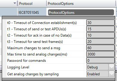
t0 - Timeout of Connection establishment(s) – Maximum waiting time, in seconds, for a
client TCP/IP to establish a connection with the LISTENING port. After this time, this driver
actively closes the TCP/IP socket and restarts it to a LISTENING state. Allowed values are
between 1 and 255.

t1 - Timeout of send or test APDUs(s) - Maximum acceptable time, in seconds, for the
slave to send regular or test APDUs after receiving the START DT sending confirmation.
Allowed values are between 1 and 255.

t2 - Timeout for ack in case of no data(s) - Maximum waiting time, in seconds, for a
pending acknowledgement before sending an acknowledgement for the last received
message. A message with the sequence number of the last one received. Values from 1 to
255 are allowed. In addition, t2 must be shorter than t1.

t3 - Timeout for send test frames(s) - Maximum waiting time, in seconds, for the arrival of
any information (in case of a TCP-IP connection already established) before sending a
TEST-FR. The values are allowed are from 1 to 255.

Maximum Changes to send a message - To improve communication module performance
when sending changes in analog measurements, this number can be set as the maximum
number of changes that must be accumulated to be sent in a single message, instead of
sending a measure in each message. A number considered good is 30 measures, which is
the default value. This accumulation is used when tag changes, in measurements, are
received by the communication module as events (AccessType with WriteEventEnable).

Max time to send analog changes (ms) – This defines the maximum waiting time for
sending a message with changes in analog measurements. If, since the start of
accumulation of measurements for the same message, this time expires before the arrival
of the number of measures defined above, this module will send the message with the
measures that have already arrived. This time is set to 3 seconds. If the “Get analog changes
by sampling mode” option is used (see below), this is the time to be used as the interval
between two samplings.

Password for commands : In order to increase security when sending commands, normally
initiated only by a change in the state of a tag, it is possible to specify in the Client modules
a password of up to 9 digits for the command. Here in this server module you must specify
the password used by this Server module to generate the command for the Client module
that will actually send the command to the field. This password must be the same as that
used by the module sender of this command.

Logging Level
DebugAll messages are registered in the LOG.
InfoOnly Info, Warning and Error messages are registered in the LOG.
WarningOnly Warning and Error messages are registered in the LOG.
ErrorOnly Error messages are registered in the LOG.

Get analog changes by sample - Alternatively to the mode of receiving changes of tag
values, (by using AccessType with WriteEventEnable), there’s an option to use, by the
communication module, the sampling mode of changes occurred in tags. In this mode, the
current values are checked against the last values sent periodically. This way only the
change is considered, and the new value is sent to the client, if the absolute difference
between the current value and the last one sent is greater than the Deadband attribute of
the tag. To use this mode you must use the AccessType in the Points table, for these
measurement tags, with WriteEventEnable disabled.

The time interval between each of the two checks will be as defined in the above parameter,
Max time to send analog changes (ms).


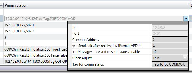
Listening Port : Number of the port used for listening client connection attempts. The standard defines port 2404 , by default. User can use custom port numbers.

NodeConnections : Defines the maximum number of parallel requests that could be sent to each node (asynchronous communication).


Node Configuration

Each node is a server station (IED). User may set a single station per channel.

Parameters

CommonAddress - Application Layer address.

w – Send ack after received w IFormatAPDUs – Number of information messages sent
spontaneously to client until it sends an “acknowledgment” with the sequence number of
the last messages it received. Allowed values are between 1 and 32767.

k – Messages received to send state variable – Maximum allowed number of pending
acknowledgements before this slave stops sending new messages. The IEC standard
recommends that w is, at most, two-thirds of the k value. Values allowed are between 1
and 32767.

Clock Adjust – Can be set as “True” to adjust the clock on this server computer or “False” to
make no adjustment. This module will adjust the clock by changing the machine time to
match the one that came on a synchronization message received. For this to be effective,
the master IED must send a time that comes, for example, from a GPS.

Tag for Comm status - In this field the name of an existing tag in the project can be
indicated to show success/failure in communication from a functional point of view. The
module waits for a maximum of Timeout milliseconds (defined in Protocol Options, as t2
above) for receiving a request from the client. In case of failure, the module sets the value of
this tag to ZERO. In case of success, it sets the value to ONE.

Backup Station – The same settings adjusted to the main station can be adjusted to a
backup workstation (alternative IED) if there is one in the facility.


Points Configuration

Points can be input or output points. Input points, i.e. points that are acquired by the
protocol, have basically two main parameters: point type and address. Output points used
for remote controls have an additional address field parameter to specify an output
operation. In a given IED or Node all addresses are unique no matter the kind of point.

Point Types

Scada in Slave mode implements:

  • Receiving date and time for synchronization
  • Responding to a General Interrogation request
  • Sending unsolicited information frames due to the data changes in a remote IED
  • Time tag (56 bits long)
  • Receiving single or double digital Point Commands
  • Select Before Operate Command
  • Point Value Quality analysis (QDS)

The implemented point types are defined by the data objects set out in the IEC standard, presented below:


M_SP_NA: 1 - Single-point information

  • Simple binary input point, value 0 or 1. The variant sent by the server has the timetag
    M_SP_TB (= 30) when sent spontaneously, or M_SP_NA_1 itself in the answers to General
    Interrogations. In registration, only this type is used.


M_DP_NA: 3 - Double-point information

  • Dual input point, which can assume states 0 to 3. Normally used in the signaling of states of
    switches and circuit breakers. The variant sent by the server has the timetag M_DP_TB (=
    31) when sent spontaneously, or M_DP_NA itself in the answers to General Interrogations.
    In registration, only this type is used.


M_ST_NA: 5 - Step position

  • Step or step value, in the range from -64 to +63, mainly used for transformer tap position or
    other position information. The variant sent by the server has a “timetag” when sent
    spontaneously, or the M_ST_NA itself in the answers to General Interrogations. In
    registration, only this type is used.


M_BO_NA: 7 - Bitstring with 32 bits

  • Binary state information as a 32-bit string. No manipulation is done by the driver. The
    setting is treated as a long number. The variant sent by the server has the “timetag”
    M_BO_TB (= 33) when sending spontaneously, or M_BO_NA itself in the answers to General
    Interrogations. In registration, only this type is used.


M_ME_NA: 9 - Measured value, normalized

  • Standard analog 16-bit signal measurement. Value between -32768 and +32767. It is
    calculated as a real number between 0 and 1 before being assigned to a tag in real time.
    Scaling must be used to reproduce the value in the engineering unit. The variant sent by the
    server is the same without the timetag M_ME_NA for both the changes and the replies to
    the General Interrogations. In registration, only this type is used.


M_ME_NB: 11 - Measured value, scaled value

  • Scalar analog measurement used for transmitting analog quantities. Also 16-bit, value
    between -32768 and 32767. The variant sent by the server is the same without the timetag
    M_ME_NB for both changes and replies to General Interrogations. In registration, only this
    type is used.

M_ME_NC: 13 - Measured value short floating point

  • Analog measurement in a fractional real number format, used for transmission of analog
    quantities. The measurements are 32-bit fields in the IEEE STD 754 format, which
    implements floating-point numbers. The variant sent by the server is the same without the
    timetag M_ME_NC for both changes and replies to General Interrogations. In registration,
    only this type is used.


M_IT_NA: 15 - Integrated totals

  • Full analog measurement with signal. Measures with 32 bits integer. The variant sent by the
    server is the same without the timetag M_IT_NA for both changes and replies to General
    Interrogations. In registration, only this type is used.


C_SC_NA: 45 - Single command

  • Command for a single point (1 bit). Command details can be chosen by clicking the button
    to the right of the field. It’s also possible to enter the number which is the command code
    resulting from the choice of details directly. Each point will be statically parameterized in
    the POINTS table, so that one point must be set for opening and one for closing one-bit
    switches.


C_DC_NA: 46 - Double command

  • Command for a double point (2 bits). Command details can be chosen by clicking the button
    to the right of the field. It’s also possible to enter the number which is the command code
    resulting from the choice of details directly. Each point will be parameterized statically in
    the POINTS table, so that one point must be configured for opening and another for closing
    two-bit switches.


C_RC_NA: 47 - Regulating step command

  • Command for setting step, usually used to send pulses to step switching transformers up
    and down. Command details can be chosen by clicking the button to the right of the field.
    It’s also possible to enter the number which is the command code resulting from the choice
    of details directly. Each point will be parameterized statically in the POINTS table, so that
    one point must be configured to step the position up and another to step it down.


C_SE_NA: 48 - Set point command, normalized value

  • For sending 16-bit set points, normalized to IEDS that support this type of command.
    The value to be sent is the one indicated by the tag whose address was sent in the
    command.


C_SE_NC: 50 - Set point command, short floating point value

  • For sending 32-bit set points, in a IEEE STD 764 floating point format, to IEDs that support
    this type of command. The value to be sent is the one indicated by the tag whose address
    was sent in the command.

C_BO_NA: 51- 32-bit Write Bitstring

  • For writing on the IED server binary state information as a 32-bit string. No manipulation is
    made by the driver. The setting is treated as a long unsigned number. The value to be sent is
    the one indicated by the tag whose address was sent in the command. The type of the tag
    must be “long” or AnalogInt, which is a 32-bit integer.

Point Address

The completion of point addresses is performed in the engineering environment, in Edit>
Devices> Points.

The Address field to be filled in during point registration is what the standard calls
“Information Object Address.” This is a number of 3 bytes. For a given IED (node), it must be
unique.

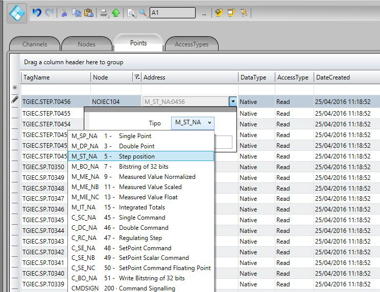
As shown in the figure below, clicking once on the row of the address column will open a
window to select the type and address of the point. Clicking on the type will open a window
with all types of points supported:
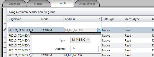
To select Type:

Command Parameter

The command parameter applies only to commands types and is a one-byte code which
details what and how the IED should execute the command. In this implementation, as the
user registers a point typed as command output, this field shows up to the user. If the user
already knows the code, then he or she can just type it in the field. Otherwise, they must
click on the button to the right of the window to display a dialog to choose the actions and
details of commands.

Parameter Configuration

The codes generated by choosing the items in the window parameter setting command are
formed by calculating the sum of two parts (A and B), with the first part indicating the
action, and the second indicating the details of the transaction, as defined below:

For Single Command C_SC_NA:

  • 0 = Turn off (A)
  • 1 = Turn on (A)
  • 0 = No detail (B)
  • 4 = Short Pulse (B)
  • 8 = Long Pulse (B)
  • 12 = Persistent Signal (B)

For Double Command C_DC_NA:

  • 1= Turn off (A)
  • 2= Turn on (A)
  • 0 = No detail (B)
  • 4 = Short Pulse (B)
  • 8 = Long Pulse (B)
  • 12= Persistent Signal (B)

For Voltage Regulation C_RC_NA:

  • 1 = Down (A)
  • 2 = Up (A)
  • 0 = No detail (B)
  • 4 = Short Pulse (B)
  • 8 = Long Pulse (B)
  • 12 = Persistent Signal (B)

The remaining options are the Select command - just select the device to be controlled, or
the Execute command – which means sending the action command itself. For the Select ,
128 must be added to the code obtained from the sum of the parts A and B.

Example: code = 9 in a simple command means Long Pulse to Turn on the remote device.


Using the parameter in the Server (Slave) protocol

When receiving a master (client) command, the server runs according to the parameter
coming from the message. The parameter defined on the data base of the server is not
used and can be set in any way desired by the user.

The behavior of the server when executing a command is as follows:

Select / Execute

SELECT – There will be no execution per se, i.e., there will be change in server memory. A
message will be sent to the log (Trace), indicating the SELECT mode, if the output
point was actually found on the server. If the point doesn’t exist, a “POINT NOT
FOUND” error message will appear in the log.

EXECUTE - The command will be executed normally and an “EXECUTE” message will appear
in the log.

Detail Options – Option B

0 – No detail – The destination point state of the command will be toggled (if zero, it
changes to 1 and if 1 it changes to zero), whatever the value of part A.
4 – Short Pulse – The value of part A will be placed at the destination point, maintained this
way for 100 ms, and then restored to its original value.
8 – Long Pulse – The value of part A will be placed into the destiny point, maintained this
way for 1000 ms, and then restored to its original value.
12 – Persistent Signal – The value of part A will be placed at the destination point and kept
this way.

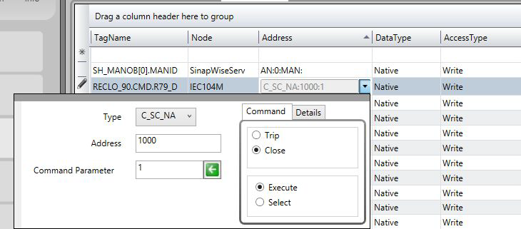
In order to set up the Scada with output parameters, follow the procedure below: (1) Click the right border of the address once to show three command parameters in the command tab:

  • a. Type
  • b. Address
  • c. Command parameter

And the command options:

  • a. Trip
  • b. Close
  • c. Execute
  • d. Select

(2) Select the desired options and by clicking on the left arrow ( ), the binary value
corresponding to the selection will be loaded in the command parameter:


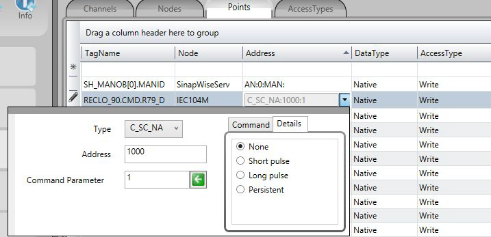
If detailing the type of signal to be sent is necessary, before clicking on the left arrow click
on details and, as in the figure below, select the type of the output signal:

Access Type

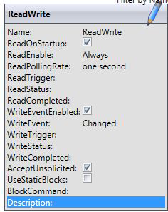
Since this is a slave (server) communication module, it requires a few specific characteristics
of its own in order to parameterize the Access Type field in the Points table:

For reading-type points: (using WriteEvents enabled, receiving changes as events)

  • M_SP_NA: 1 - Single-point information
  • M_DP_NA: 3 - Double-point information
  • M_ST_NA: 5 - Step position
  • M_BO_NA: 7 - Bitstring with 32 bits
  • M_ME_NA: 9 - Measured value, normalized
  • M_ME_NB: 11 - Measured value, scaled value
  • M_ME_NC: 13 - Measured value Float
  • M_IT_NA: 15 - Integrated totals


The Access Type must be defined with:

  • ReadOnStartup= On
  • ReadPooling= Always
  • ReadPoolongRate: 500 mili
  • WriteEnable = On
  • WriteEvent= Changed
  • AccepUnsolictited = On


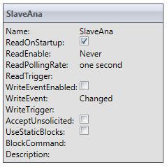
For reading-type points, used as analog measures (Using Get analog changes by sampling mode)

  • M_ME_NA: 9 - Measured value, normalized
  • M_ME_NB: 11 - Measured value, scaled value
  • M_ME_NC: 13 - Measured value Float
  • M_IT_NA: 15 - Integrated totals


AccessType must be defined as shown in the SlaveAna figure below.

  • ReadOnStartup= On
  • ReadPooling= never
  • ReadPoolongRate: one second
  • WriteEventEnable = off
  • WriteEvent= Changed
  • AccepUnsolictited = off

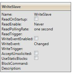
For output commands-type points:

  • C_SC_NA: 45 - Single command
  • C_DC_NA: 46 - Double command
  • C_RC_NA: 47 - Regulating step command
  • C_SE_NA: 48 - Set point command, normalized value
  • C_SE_NC: 50 - Set point command, 32 bits floating point
  • C_BO_NA: 51- Write Bitstring of 32 bits


AccessType must be defined as: (WriteSlave)

  • ReadPooling = Never
  • WriteEventEnable = off
  • WriteEvent= Changed


  • No labels