The IEC870501S protocol implements communication with the client stations compatible with this protocol, acting as a slave station (server).
Communication Driver Name: IEC8705101S
Current Version: 2016. 2.1
Implementation DLL: T.ProtocolDriver.IEC8705101S.dll
Protocol: IEC-60870-5-101 Slave standard protocol
Interface: Serial
Client types supported: Any client compatible with IEC-60870-5-101
Communication block size: Maximum 250 bytes, FT 1.2 format
Protocol Options: Sizes in bytes of addresses, password for commands, timeouts, and type of timestamp
Multi-threading: User defined. One thread for all nodes, by default
Max number of nodes: User defined
PC Hardware requirements: Standard Serial Port
Data Objects Supported (ASDUs)
The protocol uses the ASDUs defined for IEC-60870-5-101 and their data object types. It only supports serial communication.
- M_SP_NA: 1 - Single-point information
- M_DP_NA: 3 - Double-point information
- M_ST_NA: 5 - Step position
- M_BO_NA: 7 - Bitstring with 32 bits
- M_ME_NA: 9 - Measured value, normalized
- M_ME_NB: 11 - Measured value, scaled value
- M_ME_NC: 13 - Measured value Float
- M_IT_NA: 15 - Integrated totals
- C_SC_NA: 45 - Single command
- C_DC_NA: 46 - Double command
- C_RC_NA: 47 - Regulating step command
- C_SE_NA: 48 - Set point command, normalized value
- C_SE_NC: 50 - Set point command, 32 bits floating point
- C_BO_NA: 51- 32-bit Write Bitstring
It also uses all the 24-bit and 56-bit timestamp variants of the above ASDUs. The above codes are used in point registration. When sending unsolicited changes, the variants with a date and timestamp are used for digital points (SP, DP, ST and BO) as defined in the protocol option. Analog measurements are always sent without timestamp.
General Operation
The IEC-870-5-101 protocol is implemented on Server mode in the initial state, waiting for the reset and status request commands on the Link Layer of IEDs that implement the Client or Master IEC-870-5-101 protocol. The frame used for message exchange is FT 1.2, unbalanced version (slave does not send unsolicited events). Various parameterizations are available to accommodate different profiles of protocol implementations, known for the
certain amount of flexibility defined in the standard itself.
This module responds to read requests of analog and digital variables, event transmission and command execution. The implementation has the following characteristics:
- Responds to cyclic read requests (general sampling) of single/double and analog digital points and Counters
- When Class 1 and Class 2 are requested, it sends changes of digital point states and changes in analog measurements, considering dead band and time for integrity.
- Alternatively it uses 24 or 56-bit time tags when sending changes in SP, DP, ST and BO
- Accepts commands for single and double digital points, regulating step, BitString and set points for analog measurements
- Supports direct, select and select and execute commands
- Point quality analysis (QDS)
Channel Configuration
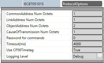
Protocol Options
CommonAddress Num Octets – Number of bytes used in the slave station address for the application layer. It can be 1 or 2 bytes.
LinkAddress Num Octets – Number of bytes used in the slave station address for the link layer. It can be 1 or 2 bytes.
ObjectAddress Num Octets - Number of bytes used for data object address. It can be 1, 2 or 3 bytes.
CauseOfTransmission Num Octets - Number of bytes used to show the cause of data transmission. It can be 1 or 2 bytes.
Password for commands – This parameter should be used if the commands received here are sent by another communication channel that is also using a password to send the commands. In this case, the password defined here must be the same as the one defined for the protocol that will send the command.
Timeout(ms) - Waiting time in milliseconds for receiving a response after sending any request. It is a functional check, which does not take into account the type of request or response, it only checks if there are responses being received in the channel.
UseCP56Tags – The True option must be selected so that changes of digital points are sent using ASDUs variations that use 56-bit timestamps. Otherwise, 24-bit timestamps will be used.
Logging Level – You can choose from this list the logging mode created by the communication module.
| Logging Level |
|---|
| Debug | All messages are registered in the LOG. |
| Info | Only Info, Warning and Error messages are registered in the
LOG. |
| Warning | Only Warning and Error messages are registered in the LOG. |
| Error | Only Error messages are registered in the LOG. |
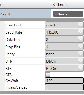
Interface
The communication interface used is called CustomSerial, as it is implemented not through the basic SCADA libraries but through a library integrated with the communication protocol itself.
Settings
Serial Channel:
Com: Serial communication port used;
- BaudRate
- DataBits: 8
- StopBits: 1 or 2
- Parity: None, Even, Odd;
- DTR: on, off
- RTS: on, off
- CTS: on, off
- Port configurations must be compatible with those of Client IED:
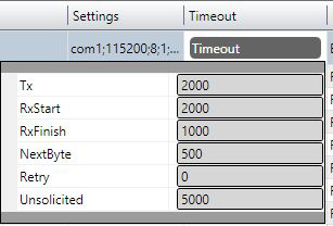
Timeouts
Usually, default timeout settings are appropriate for most installations. If necessary, the values in milliseconds defined in the figure below can be changed.
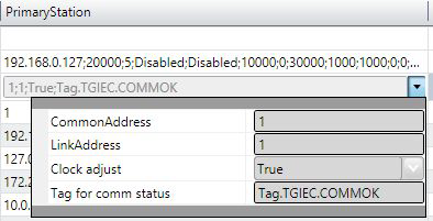
Node Configuration
Each node is a server station. The user can configure a single server station for each
channel.
Parameters
Common Address - IED application layer address
LinkAddress – IED link layer address
Clock Adjust – In some implementations, in which there is no GPS coupled to the Slave IED (server), the client can send a synchronization request, by which the communication module will change the date-time of the computer in which it is running .
Tag for Comm status - In this field, it is possible to indicate the name of an existing tag in the project to show success/failure in communication from a functional point of view. When requests are made, the module waits for a maximum of Timeout milliseconds (defined in Protocol Options, above) to receive a response. In case of failure, the system sets the value of this tag to ZERO. In case of success, the system sets the value to ONE.
Backup Station - Not used for server mode stations.
Point Configuration
Points can be input or output points. Input points, i.e. points that are acquired by the client protocol, have basically two main parameters: point type and address. Output points are used for remote controls, and have an additional parameter used to specify the type of output operation. On the address map of an IED, the addresses are never repeated. The addresses are unique regardless of the type of point.
Point types
The communication module in Slave mode implements:
- Receiving date and time for synchronization
- Response to general interrogation request
- Sending unsolicited information frames due to data changes in the memory
- Time tag 24 or 56 bits long
- Receiving single or double digital point command, Regulating steps and BitStrings
- Receiving set point commands for analog points
- Receiving select before operate command
- Point quality analysis (QDS)
The point types implemented are defined by the data objects defined in the IEC standard, as shown below.
| Data Objects | Description |
|---|
| M_SP_NA: 1 - Single-point information | Simple binary input point, value 0 or 1. The variants sent by the server have the "timetag" M_SP_TA (= 2) or M_SP_TB (= 30) when sent spontaneously, or M_SP_NA_1, without timestamp, in responses to a General Interrogation. In the registration, only this type is used. |
| M_DP_NA: 3 - Double-point information | Double input point, which can assume states 0 to 3. Usually used for signaling states of switches and circuit breakers. The variants sent by the server have the “timetag” M_DP_TA (=4) or M_DP_TB (= 31) when sent spontaneously, or M_SP_NA_1, without timestamp, in responses to a General Interrogation. In the registration, only this type is used. |
| M_ST_NA: 5 - Step position | Step value, ranging from -64 to +63, mainly used for transformer step position or other position information. The variants sent by the server have the “timetag” M_DP_TA or M_DP_TB when sent spontaneously, or M_SP_NA_1, without timestamp, in responses to a General Interrogation. In the registration, only this type is used. |
| M_BO_NA: 7 - Bitstring with 32 bits | Status information as a binary string of 32 bits. No manipulation whatsoever is made by the driver. The configuration is treated as a long number. The variants sent by the server have the “timetag” M_BO_TA or M_BO_TB(=33) when sent spontaneously, or M_BO_NA in responses to a General Interrogation. In the registration, only this type is used. |
| M_ME_NA: 9 - Measured value, normalized | Standard analog measurement using a 16-bit signal. Value between -32768 and +32767. It is calculated as a real number between 0 and 1 before being assigned to the tag in real time. Scaling should be used to reproduce the value in engineering units. The variant sent by the server is the same without the “timetag” M_ME_TA both for changes and responses to a General Interrogation. In the registration, only this type is used. |
| M_ME_NB: 11 - Measured value, scaled value | Scalar analog measurement used for transmission of analog quantities. Also a 16 bit value between -32768 and 32767. The variant sent by the server is the same without the “timetag” M_ME_NB both for changes and responses to a General Interrogation. In the registration, only this type is used. |
| M_ME_NC: 13 - Measured value short floating point | Analog measurement in a fractional real number format, used for transmission of analog quantities. The measurements are 32-bit fields in the IEEE STD 754 format, which implements floating-point numbers. The variant sent by the server is the same without\ “timetag” M_ME_NC both for changes and responses to a General Interrogation. In the registration, only this type is used. |
| M_IT_NA: 15 - Integrated totals | Integer analog measurement signal. Measurements with a 32-bit integer. The variant sent by the server is the same without the “timetag” M_IT_NA both for changes and responses to a General Interrogation. In the registration, only this type is used. |
| C_SC_NA: 45 - Single command | Single point command (1 bit). Details of the command can be selected by clicking the button on the right side of the field. It is also possible to directly enter the number that is the command code resulting from the selection of the details. Each point will be statically parameterized in the POINTS table, in a way that one point must be configured for opening and another for closing 1-bit switches. |
| C_DC_NA: 46 - Double command | Double point command (2 bits). Details of the command can be selected by clicking the button on the right side of the field. It is also possible to directly enter the number that is the command code resulting from the selection of the details. Each point will be statically parameterized in the POINTS table, in a way that one point must be configured for opening and another for closing 2-bit switches. |
| C_RC_NA: 47 - Regulating step command | Command for setting step, usually used to send pulses to step switching transformers up and down. Details of the command can be selected by clicking the button on the right side of the field. It is also possible to directly enter the number that is the command code resulting from the selection of the details. Each point will be statically parameterized in the POINTS table, in a way that one point must be configured to step up and another to step down the step position. |
| C_SE_NA: 48 - Set point command, normalized value | Used to send 16-bit set points, normalized to IEDs that support this type of command. The value to be sent is the one indicated by the tag whose address was sent in the command. |
| C_SE_NC: 50 - Set point command, short floating-point value | Used to send 32-bit set points in an IEEE STD 764 floating-point format, to IEDs that support this type of command. The value to be sent is the one indicated by the tag whose address was sent in the command. |
| C_BO_NA: 51- 32-bit Write Bitstring | Used to write binary state information as a 32-bit string on the IED server. No manipulation whatsoever is made by the driver. The setting is treated as a long unsigned number. The value to be sent is the one indicated by the tag whose address was sent in the command. The tag type must be “long” or AnalogInt, which is a 32-bit integer. |
Point Address
The Address field to be filled in during point registration is what the standard calls “ Information Object Address. ” This is a number with a specific number of bytes as defined in the Protocol Options.
Command Parameter
The command parameter is, for the types of commands implemented, a one-byte code which details what and how the command is to be executed by the IED. In this implementation, when a point with an output command type is registered, this field appears to be filled in. If you already know the code you want to use, simply type it in the
field. If not, click on the button on the right side of the field in order to display the window with the actions and details that can be chosen.
Parameter Settings
The codes generated after choosing the items in the window for setting the command parameter are formed by the calculation of the sum of two parts (A and B), the first indicating the action, and the second indicating the details of the operation, as defined below:
For Single Command C_SC_NA:
- 0 = Turn off (A)
- 1 = Turn on (A)
- 0 = No detail (B)
- 4 = Short Pulse (B)
- 8 = Long Pulse (B)
- 12 = Persistent Signal (B)
For Double Command C_DC_NA:
- 1 = Turn off (A)
- 2 = Turn on (A)
- 0 = No detail (B)
- 4 = Short Pulse (B)
- 8 = Long Pulse (B)
- 12 = Persistent Signal (B)
For Regulating Step Command C_RC_NA:
- 1 = Step Down (A)
- 2 = Step Up (A)
- 0 = No detail (B)
- 4 = Short Pulse (B)
- 8 = Long Pulse (B)
- 12 = Persistent Signal (B)
The remaining option is the Select type command – to select the device to be controlled; or the Execute type command – to send the proper action command. If the Select command is chosen, add 128 to the code obtained from the sum of parts A and B.
Example: code = 9 in a single command means Long Pulse to Turn on the device.
Using the parameter in the Server (Slave) protocol
By receiving a command from the master (client), the server runs according to the parameter coming from the message. The parameter defined in the server database is not used and can be configured in any way.
The behavior of the server when running the command is explained below.
Select / Execute
- SELECT - There will be no execution, i.e., there will be no change in server memory. A message will be sent to the log (Trace), indicating the SELECT mode, if the output point was actually found on the server. If the point does not exist a "POINT NOT FOUND!" error message will appear in the log.
- EXECUTE - The command will be executed normally and an “EXECUTE” message will appear in the log indicating the event.
Detail Options – Option B
- 0 – None - The destination point state of the command will be toggled (if zero, it changes to 1, and if 1, it changes to zero), whatever the value of part A.
- 4 - Short Pulse – The value of part A will be placed at the destination point, and maintained this way for 100 ms, and after that the original value will be restored.
- 8 – Long Pulse – The value of part A will be placed at the destination point, and maintained this way for 1000 ms, and after that the original value will be restored.
- 12 - Persistent – The value of part A will be placed at the destination point, remaining unchanged.
Access Type
Being a communication module in slave (server) mode, it requires a few characteristics of its own for the parameterization of the Access Type field of the Points table:
For reading-type points:
- M_SP_NA: 1 - Single-point information
- M_DP_NA: 3 - Double-point information
- M_ST_NA: 5 - Step position
- M_BO_NA: 7 - Bitstring with 32 bits
- M_ME_NA: 9 - Measured value, normalized
- M_ME_NB: 11 - Measured value, scaled value
- M_ME_NC: 13 - Measured value Float
- M_IT_NA: 15 - Integrated totals
The Access Type must be defined with:
- ReadOnStartup= On
- ReadPooling= Always
- ReadPoolongRate: 500 milli
- WriteEnable = On
- WriteEvent= Changed
- AccepUnsolictited = On
For command-type points:
- C_SC_NA: 45 - Single command
- C_DC_NA: 46 - Double command
- C_RC_NA: 47 - Regulating step command
- C_SE_NA: 48 - Set point command, normalized value
- C_SE_NC: 50 - Set point command, 32 bits floating point
- C_BO_NA: 51- 32-bit Write Bitstring
The Access Type must be defined with:
- ReadPooling = Never
- WriteEnable = Not marked
- WriteEvent= Changed