Page Tree
Previous Releases
The Drawing tab has the following controls to create, format, and configure displays:
To configure dynamic graphic displays, click on the "Draw" icon in the main menu.
The Appearance parameters dictate the brush style and color used when drawing objects in the display. Clicking on the Fill option lets you specify the colors, gradients, or objects with which to fill the graphic.
The DisplaySettings dictate the attributes of the display. Displays can be configured as Pop Ups, Dialogs, or as normal page displays.
Like with any graphical object, displays can have varying colors and patterns, borders, titles etc.
One special feature is that you can specify that a transition animation is used when entering the display.
Vertical toolbar commands | |
Commands | Description |
|
|
|
|
| The Hand tool can be used to modify the view window. Click once on the display background and hold down the left mouse button. Then, shift the display to the desired position. |
Geometric objects tools | Right-click to end the use of each tool. |
| Creates a rectangle object. |
| Creates an ellipse object. |
| Creates a polygon object. |
| Creates a polyline object. |
| Creates a button object. |
| Creates a label box. |
| Creates a text output object. |
| Creates a text input/output (I/O) object. |
| Creates a check box object. Right-click this button to access the following tools: |
| The symbol library includes both built-in and user-defined symbols. |
| The Symbol Factory is an external symbol library that contains a lot of symbols created to be used in the projects. |
| Insert an image to be used in the project. |
| Creates a Web Browser object. Hover over this button to access the following tools: |
| Creates an alarm window. Position the alarm window and double-click to configure the alarm window settings. For more information, see Configuring an Alarm Window below. |
| Creates an Alarm Area control that lets you view the existing alarm tree. |
| Creates a trend window. Position the trend window and double-click to configure the trend window settings. For more information, see Configuring a Trend Window below. |
| Creates a drilling chart trend window. Position the trend window and double-click to configure the trend window settings. For more information, see Configuring a Trend Window below. |
| Creates a data grid window. Position the data grid window and double-click to configure the data grid window settings. For more information, see Configuring a DataGrid Window below. |
Horizontal toolbar commands | |
Commands | Description |
| Grid definition |
| Screen Zoom |
| Group |
| Ungroup |
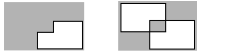
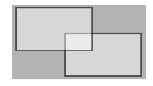
| Union |
| Intersect |
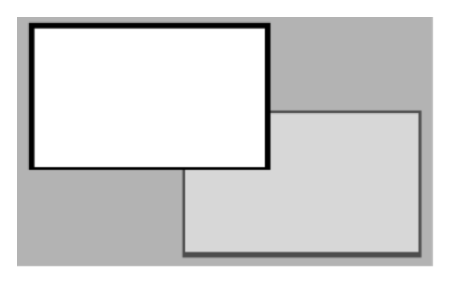
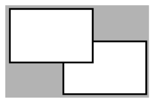
| Exclude |
| Exclusive-Or |
| AlignLeft |
| AlignHorizontalCenter |
| AlignRight |
| AlignTop |
| AlignVerticalCenter |
| AlignBottom |
| Move To The Front |
| Move To The Back |
| Change Z-Order |
| Resize Width |
| Resize Height |
| SpaceEvenlyHorizontal |
| SpaceEvenlyVertical |
| FlipHorizontally |
| Flip Vertically |
| Lock element |
| Unlock element |
| Unlock All Elements |
| Show All Elements |
| Hide Selected Element |
Examples
Here you will see examples showing the functionality of the commands of the horizontal toolbar.
The shapes used can be any object without dynamics, like polygons, ellipses, or rectangles.
Union ![]() and Intersect
and Intersect ![]()
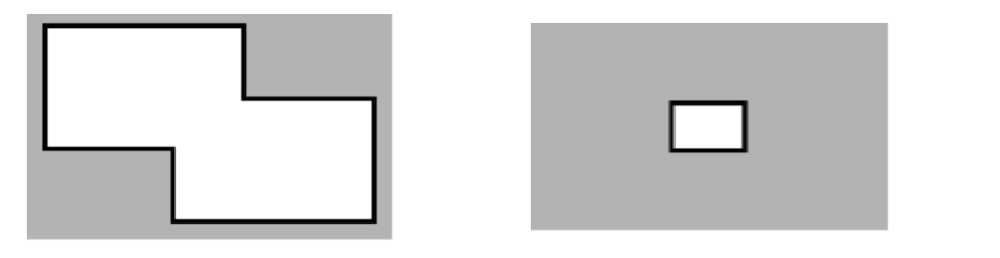
Exclude ![]() and Exclusive-Or
and Exclusive-Or ![]()