Page Tree
Previous Releases
FactoryStudio has wonderful features that help to improve productivity when you create graphical displays in an application. The drawing tools allow you to easily manage symbols, image files, import objects from a 5000 objects gallery, create your own symbols with dynamic properties, and map tags and templates to its default graphical user interface.
There are three main repositories for reusable components: the Images, the Symbol Factory library, and the Local Symbols Gallery. Let's explore each one.
Images: Used to insert an external image file (like an icon, wallpaper, object, or a background image) from your computer to the project configuration. You can manage the imported images on Edit > Displays > Resources. After the image is imported, you no longer need the original file. Images can be used as color brushes for any drawing object, and they can even be used as "color" or the ColorFill dynamic attributes.
Symbol Factory: This is an extensive library of elements, with more than 5,000 symbols that use vector graphics, that you can use for creating your displays or use as a template to create your own custom symbols. These objects can be applied statically, as an image or icon. You can add Dynamics and save them to the Local Symbols library.
Smart Symbols: These are the most frequently used symbols. They include the symbols you create in a project and a library of more than 500 symbols designed specifically for FactoryStudio. The symbols in this library can be synchronized with the library. When you change a symbol in this library, the change will be automatically applied to all displays using that symbol. Local Symbols can have dynamics properties that you can easily map to tags in displays; they can also be defined as the default graphical representation of tags.
You can import any image file in the Edit > Displays > Resources tab. This creates a repository of images for the application that is stored inside the project database file. You do not need the original files anymore. These images can be used to be the Fill of an object, such as rectangles, ellipses, LabelBoxes, paths, page background, or target color in runtime dynamics using colors.
If you need to update an image with a new version, you can replace it, and it will be updated throughout the application. Be sure to keep the resource name the same.
You can use any image file to fill or "paint" an object when you create displays in Draw > Drawing.
You can import the following file types:
To manage resources:
Column | Description |
Name | Edit the default name. |
Description | Enter a description of this image. |
Folder | Specify the folder where the resource is. |
ResourceType | Specify the type of the resource. |
Dimension | Read-only. Show the dimension of the resource file |
Size | Read-only. Show the size of the resource file |
Adding an image to a display
Typically, you should use UNIFORM or FILL for image stretching. The image (using the Appearance menu to the left) can be applied to any graphical shape in the display.
The symbols from the Symbol Factory are efficient and well designed vector graphic images. If you need an object like a pump or a valve in your application, open the library and browse for the element or search by name. The difference in symbols from the Symbol Factory and Local Symbols is that the symbols from the Symbol Factory, once included in a display, become part of that display and have no further connection with the library. In contrast, Local Symbols can keep an active link with the library and can have dynamic properties.
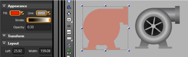
Adding color change animation to Symbol Factory elements
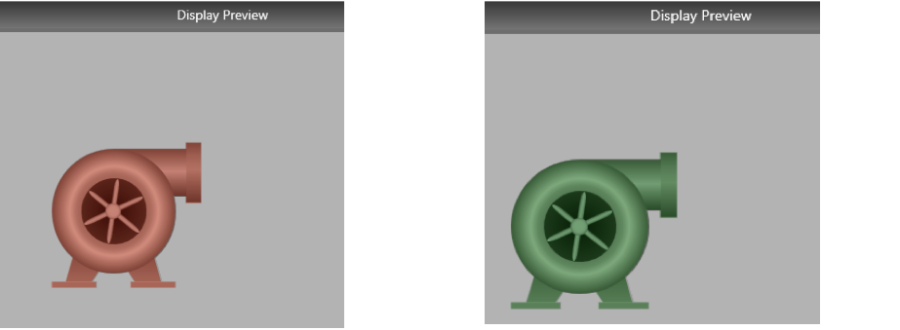
If you want to insert a color change animation without changing anything on the symbol, copy the symbol and overlay a transparent image on top of your image.
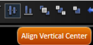
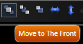
For example, suppose we have two pumps. To insert a simple animation that shows when the pump is ON or OFF, follow these steps:

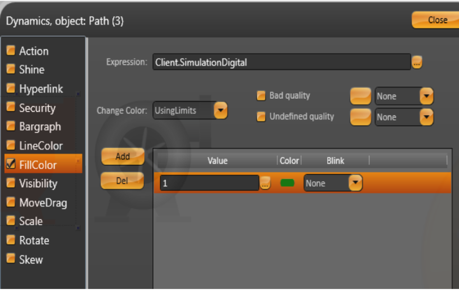
Use the Client.SimulationDigital to simulate a controller changing between 0 and 1.
If you want to control the value yourself, use Client.DigitalValue or Client.NumericValue.
The Smart Symbols Library includes the most frequently used graphics. You can create symbols and add them to a project's local library. Symbols can be static images, or they can have dynamic properties and tags links.
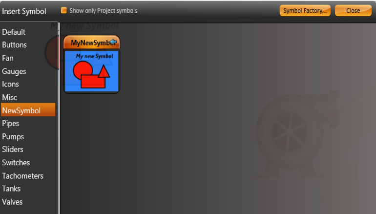
To view the symbols used in your project, do one of the following:
Creating new Symbols
You can use the drawing tools and the COMBINE commands in the horizontal toolbar to draw your own symbols.
You can also use the symbols from the Symbol Factory and click on the UNGROUP command in the horizontal toolbar to edit the imported symbols.
You can use the "Direct Selection" cursor to edit internal elements without needing to ungroup.
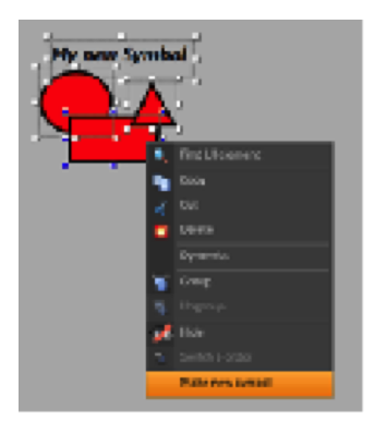
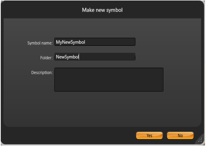
If you want to save a new symbol to the Local Symbols Library, select the object or objects that you want to be part of the symbol. Then, right-click and select "Make a new symbol".
The Local Symbol library's components may have built-in dynamic properties, and they may have an easy way to map them to the realtime tags in your application. This is explained in the following section.
If a symbol has both dynamic properties and tags, the system will automatically create label parameters for the symbol. After making a new symbol, double click the symbol to verify these parameters.
In order to Edit one of the symbols in the Local Symbol library, insert the symbol in a display, right click on it, and select "Edit Symbol". This will let you change the symbol by changing the drawing tool and locking the other elements in the page. When you finish, right-click anywhere to select Save to Library, Save Only to Local display, or to cancel your editing.
The Local Symbols are composed of the default symbols in the SymbolLibrary.tproj file and the symbols you created for your specific project. If you change, delete, or insert a symbol in the SymbolLibrary.Tproj, it will be accessible to any project on that computer. The symbols you use in your project are saved inside the PROJECT file. Therefore, they are completely independent of any external file.
Inserting a Local Symbol
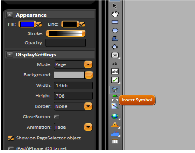
Some symbols do not have custom parameters. In this case, double clicking the symbol will show the Dynamics dialog.
Symbol Parameters
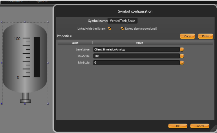
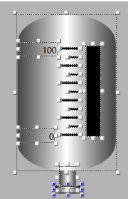
When you insert a symbol from the Symbol Library, it may have parameters. For our example, the VerticalTank symbol has the LevelValue, MaxScale, and MinScale parameters. To change the tags linked to these parameters, edit the new tag names in the dialog.
Editing and modifying symbols
Right-click on the VerticalTank symbol and select Edit Symbol. This starts the Edit mode and allows you to see all of the objects that are part of the Vertical Tank.
Click on the black rectangle to see its Dynamics.
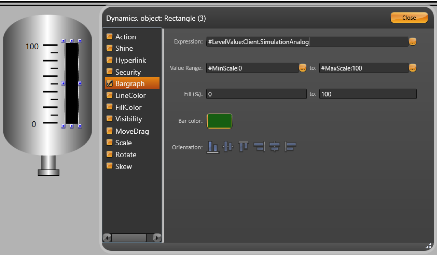
We use #<PropertyName>:TagName
This syntax will create the exposed label parameters for the symbol. This makes it easier to map any linked tags when you are using the symbol.
For this example, the symbol has the "Level","MinScale", and "MaxScale" labels. When you insert this symbol in your display, you will be able to set the values for these parameters. The default value is after the ":" character.
Example
"#LevelValue:Client.SimulationAnalog", creates a property called the "LevelValue" that has "Client.SimulationAnalog" as the default value.
You can use any name for the Label parameter.
When creating symbols, it is useful to initially map the properties to client.SimulationDigital, Client.SimulationAnalog, or Client.SimulationDouble. These are variables with values that change every second so you can see the result of your dynamic properties. You can use the internal Client.DigitalValue, Client.NumericValue, and Client.TextValue variables when you want to use a placeholder value without any built-in simulation.
In order to save the symbol, right-click on the symbol or on the display and press Save to Symbol Library, or click the Save icon on the top toolbar. Double-click on the symbol to verify its properties.
Linking Tags and Symbols
A symbol can be configured to be the default representation of a tag type. Every time you paste a tag into the Draw Environment, a symbol will be automatically created and mapped to the inserted tag.
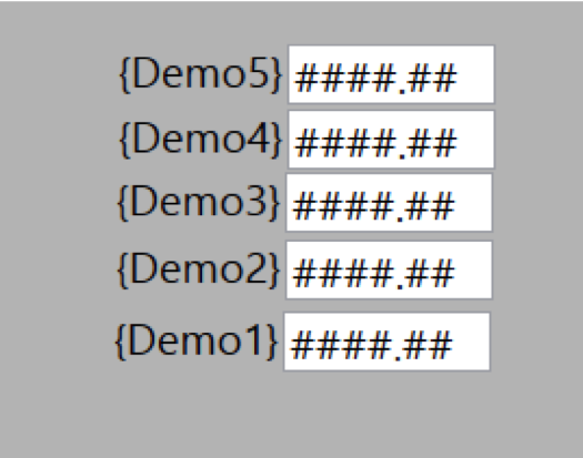
The Digital, Integer, Double, Decimal, Text, DateTime, and TimeSpan tag types have the name of the tag and an input/output text box as their default visualization. To select multiple lines in Edit>Tags>Objects, click on a line and hold down shift while clicking on another line to mark a range. The system will automatically create one object for each of the tags.
If you want to change any of the properties for the objects that were created, select all the TextBox objects by clicking and dragging over the display. Select the area with the objects and double-click on any selected object to open the "Edit Combined Dynamics" dialog.
Hint
The lines in Edit > Tags > Objects can be copied to Excel. Add the Left and Top columns to the Excel table. Then, copy/paste the table and its header column to the display. After this, the system will position the objects using the coordinates found in the table.
If you create a symbol with one dynamic parameter, and save it with the name "Integer", that will became the default visualization for the "Integer" tags. The same applies to any tag type. If you create a symbol with one dynamic parameter and save it with a name, it with because the default visualization for any tag with that name. For example, a symbol saved with the name Integer will become the default visualization for the "Integer" tags.
Mapping a Symbol to a Tag Template
You can define a symbol to be the default view for a tag template.
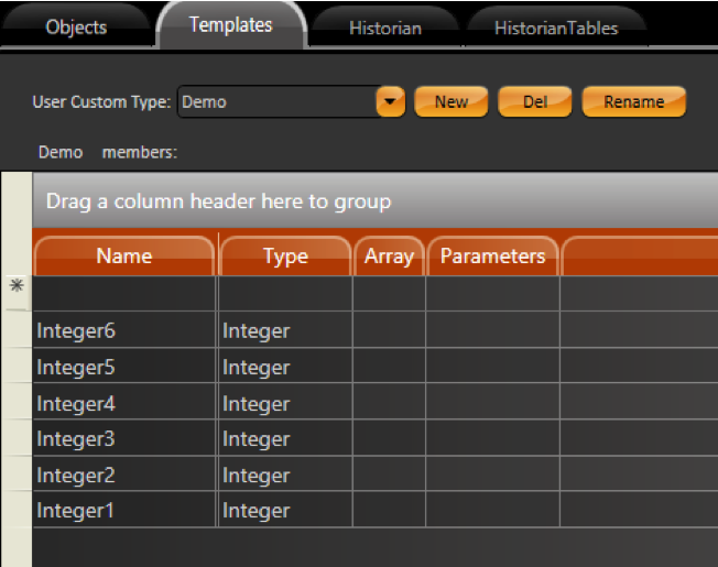
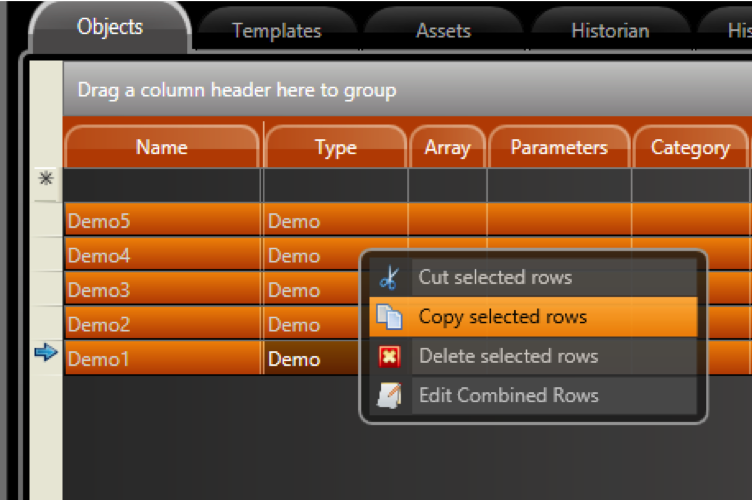
Go to Edit > Tags > Objects and create tags with Demo type.
When inserting tags of this template type, the system will look for a symbol with the same name of the template. If a match is found, the symbol is created and linked to the tag you inserted in the display.
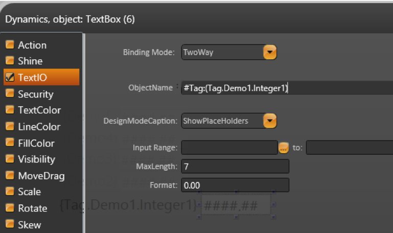
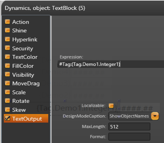
If you create symbols using only Tag Elements and not expressions, you do not need to explicitly use the full syntax: #Label:(tag.Demo).Integer1 to define the label parameters. If you just use your tag in the object's dynamic properties and execute the Make Symbol command, the system will automatically search for tags in the symbol and create the related parameters. When using expressions or when having multiple tags and templates in the same symbol, you must explicitly use the hash tag # and the parentheses in order to define the scope of your symbol's customizable parameters.
Linking Tags and Symbols using Categories
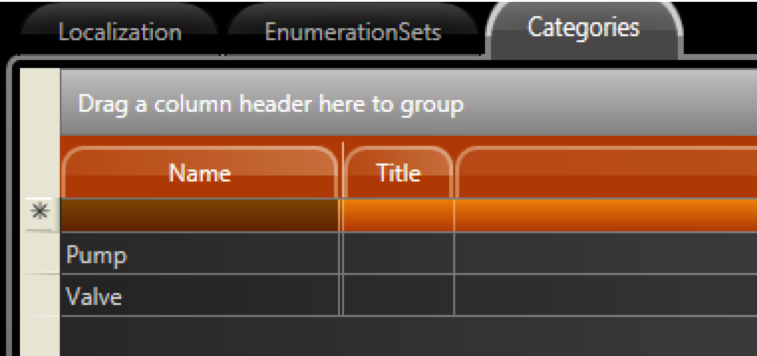
You can map a symbol to a group of tags, but you do not have to make the symbol map to all of the tags with the same type. To do this, use the Category column to link which symbols should be used as the default interface for each group of tags.
If the Category column is not visible, right-click on any Column name and select columns you want to see.
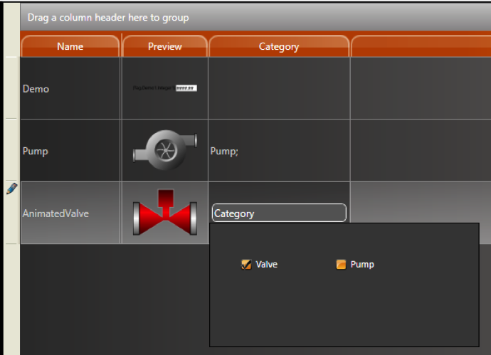
Go to Edit > Tags and define the category for the tags.
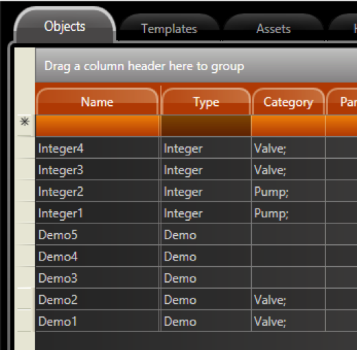
Select all of the tags and copy/paste them into the Draw Environment. Each tag will map to the respective symbol, according to the association defined in the Category column.